Plane in space - the necessary information. Mutual arrangement of a straight line and a plane. a sign of parallelism of a straight line and a plane Mutual arrangement of a straight line and a plane figure
The mutual position of a straight line and a plane is determined by the number of common points :
1) if a line has two common points with a plane, then it belongs to this plane,
2) if a line has one common point with a plane, then the line intersects the plane,
3) if the point of intersection of a line with a plane is removed to infinity, then the line and the plane are parallel.
Tasks that define mutual arrangement different geometric shapes relative to each other are called positional problems.
The straight line belonging to the plane was considered earlier.
Line parallel to plane, if it is parallel to some straight line lying in this plane. To construct such a straight line, it is necessary to specify any straight line in the plane and draw the required one parallel to it.
Rice. 1.53 Fig. 1.54 Fig.1.55
Let through the dot BUT(Fig. 1.53) it is necessary to draw a straight line AB, parallel to the plane Q, given by a triangle CDF. To do this, through the frontal projection of the point but / points BUT make a frontal projection a / in / desired line parallel to the frontal projection of any line lying in the plane R, e.g. straight CD (a / in /!!s / d /). Through a horizontal projection but points BUT parallel sd make a horizontal projection av desired line AB (av11 sd). Straight AB parallel to the plane R, given by a triangle CDF.
Of all the possible positions of a line intersecting a plane, we note the case when the line is perpendicular to the plane. Consider the properties of projections of such a line.
Rice. 1.56 Fig. 1.57
The line is perpendicular to the plane(a special case of the intersection of a straight line with a plane) if it is perpendicular to any straight line lying in the plane. To construct projections of a perpendicular to a plane in general position, this is not enough without transforming the projections. Therefore, an additional condition is introduced: a line is perpendicular to a plane if it is perpendicular to two intersecting principal lines(to construct projections, the projection condition is used right angle). In this case: the horizontal and frontal projections of the perpendicular are perpendicular, respectively, to the horizontal projection of the horizontal and the frontal projection of the frontal of a given plane in general position (Fig. 1.54). When a plane is specified by traces, the projections of the perpendicular are perpendicular, respectively, to the frontal - to the frontal trace, horizontal - to the horizontal trace of the plane (Fig. 1.55).
Intersection of a straight line with a projecting plane. Consider a straight line that intersects a plane when the plane is in a particular position.
A plane perpendicular to the projection plane (the projection plane) is projected onto it as a straight line. On this line (the projection of the plane) there must be a corresponding projection of the point at which some line intersects this plane (Fig. 1.56).
In Figure 1.56, the frontal projection of the point TO line intersection AB with a triangle CDE is determined at the intersection of their frontal projections, because triangle CDE projected onto the frontal plane as a straight line. We find the horizontal projection of the point of intersection of the line with the plane (it lies on the horizontal projection of the line). Using the method of competing points, we determine the visibility of the line AB relative to the plane of the triangle CDE on the horizontal projection plane.
Figure 1.59 shows a horizontally projecting plane P and a straight line in general position AB. Because plane R is perpendicular to the horizontal plane of projections, then everything that is in it is projected onto the horizontal plane of projections onto its trace, including the point of its intersection with the straight line AB. Therefore, in the complex drawing we have a horizontal projection of the point of intersection of the line with the plane R. According to the belonging of the point to the straight line, we find the frontal projection of the point of intersection of the straight line AB with a plane R. Determine the visibility of the line on the frontal projection plane.
Rice. 1.58 Fig. 1.59
Figure 1.58 is given complex drawing constructing projections of the point of intersection of the line AB with horizontal level plane G. Frontal plane trace G is its frontal projection. Frontal projection of the point of intersection of the plane G with a straight line AB are determined at the intersection of the frontal projection of the straight line and the frontal trace of the plane. Having a frontal projection of the point of intersection, we find the horizontal projection of the point of intersection of the line AB with plane G.
Figure 1.57 shows a plane in general position, given by a triangle CDE and front projection line AB? intersecting the plane at a point K. Frontal projection of a point - k / matches the points a / And b/ . To construct a horizontal projection of the intersection point, draw through the point K in plane CDE straight line (eg. 1-2 ). Let's construct its frontal projection, and then horizontal. Dot K is the point of intersection of the lines AB And 1-2. That is the point K simultaneously belongs to the line AB and the plane of the triangle and, therefore, is the point of their intersection.
The intersection of two planes. A straight line of intersection of two planes is defined by two points, each of which belongs to both planes, or by one point, which belongs to two planes, and the known direction of the line. In both cases, the task is to find a point common to two planes.
Intersection of projecting planes. Two planes can be parallel to each other or intersect. Consider the cases of mutual intersection of planes.
A straight line obtained at the mutual intersection of two planes is completely determined by two points, each of which belongs to both planes, therefore, it is necessary and sufficient to find these two points belonging to the line of intersection of two given planes.
Therefore, in the general case, to construct a line of intersection of two planes, it is necessary to find any two points, each of which belongs to both planes. These points determine the line of intersection of the planes. To find each of these two points, you usually have to perform special constructions. But if at least one of the intersecting planes is perpendicular (or parallel) to any projection plane, then the construction of the projection of the line of their intersection is simplified.
Rice. 1.60 Fig. 1.61
If the planes are given by traces, then it is natural to look for the points that define the line of intersection of the planes at the points of intersection of the traces of the planes of the same name in pairs: the line passing through these points is common to both planes, i.e. their line of intersection.
Consider special cases of the location of one (or both) of the intersecting planes.
The complex drawing (Fig. 1.60) shows horizontally projecting planes P And Q. Then the horizontal projection of their intersection line degenerates into a point, and the frontal projection into a straight line perpendicular to the axis ox.
The complex drawing (Fig. 1.61) shows the planes of private position: the plane R perpendicular to the horizontal projection plane (horizontal projection plane) and the plane Q- horizontal level plane. In this case, the horizontal projection of their line of intersection will coincide with the horizontal trace of the plane R, and the frontal - with a frontal trace of the plane Q.
In the case of specifying planes by traces, it is easy to establish that these planes intersect: if at least one pair of traces of the same name intersect, then the planes intersect each other.
The foregoing applies to planes defined by intersecting traces. If both planes have traces parallel to each other on the horizontal and frontal planes, then these planes can be parallel or intersect. The mutual position of such planes can be judged by constructing a third projection (third trace). If the traces of both planes on the third projection are also parallel, then the planes are parallel to each other. If the traces on the third plane intersect, then the planes given in space intersect.
The complex drawing (Fig. 1.62) shows front-projecting planes defined by a triangle ABC And DEF. The projection of the line of intersection on the frontal projection plane is a point, i.e. Since the triangles are perpendicular to the frontal projection plane, their line of intersection is also perpendicular to the frontal projection plane. Therefore, the horizontal projection of the line of intersection of triangles ( 12 ) is perpendicular to the axis ox. The visibility of the elements of the triangles on the horizontal projection plane is determined using competing points (3,4).
On the complex drawing (Fig. 1.63), two planes are set: one of which is a triangle ABC general position, the other - a triangle DEF perpendicular to the frontal projection plane, i.e. located in a private position (front-projecting). Frontal projection of the line of intersection of triangles ( 1 / 2 / ) is found based on common points that simultaneously belong to both triangles (everything that is in the front-projecting triangle DEF on the frontal projection will result in a line - its projection onto the frontal plane, including the line of its intersection with the triangle ABC. According to the belonging of the points of intersection to the sides of the triangle ABC, we find the horizontal projection of the line of intersection of the triangles. Using the method of competing points, we determine the visibility of triangle elements on the horizontal plane of projections.
Rice. 1.63 Fig. 1.64
Figure 1.64 shows a complex drawing of two planes defined by a triangle in general position ABC and horizontally projecting plane R, given by traces. Since the plane R- horizontally projecting, then everything that is in it, including the line of its intersection with the plane of the triangle ABC, on the horizontal projection will coincide with its
horizontal track. The frontal projection of the line of intersection of these planes is found from the condition that the points of the element belong to (sides) of the plane in general position.
In the case of specifying planes in general position not by traces, then to obtain the line of intersection of the planes, the point of meeting of the side of one triangle with the plane of another triangle is sequentially found. If planes in general position are not given by triangles, then the line of intersection of such planes can be found by introducing two auxiliary secant planes in turn - projecting (for specifying planes by triangles) or level for all other cases.
Intersection of a line in general position with a plane in general position. Previously, cases of intersection of planes were considered, when one of them was projecting. Based on this, we can find the point of intersection of a line in general position with a plane in general position by introducing an additional projecting mediator plane.
Before considering the intersection of planes in general position, consider the intersection of a line in general position with a plane in general position.
To find the meeting point of a line in general position with a plane in general position, it is necessary:
1) enclose a straight line in an auxiliary projecting plane,
2) find the line of intersection of the given and auxiliary planes,
determine a common point belonging simultaneously to two planes (this is their line of intersection) and a straight line.
Rice. 1.65 Fig. 1.66
Rice. 1.67 Fig. 1.68
The complex drawing (Fig. 1.65) shows a triangle CDE general position and direct AB general position. To find the point of intersection of a line with a plane, we conclude the line AB Q. Let's find the line of intersection ( 12 ) intermediary plane Q And given plane CDE. When constructing a horizontal projection of the intersection line, there is a common point TO, simultaneously belonging to two planes and a given line AB. From the belonging of a point to a straight line, we find the frontal projection of the point of intersection of a straight line with a given plane. The visibility of the elements of a straight line on the projection planes is determined using competing points.
Figure 1.66 shows an example of finding the meeting point of a straight line AB, which is a horizontal line (the line is parallel to the horizontal plane of projections) and the plane R, in general position, given by traces. To find the point of their intersection, the line AB lies in the horizontally projecting plane Q. Then proceed as in the above example.
To find the meeting point of a horizontally projecting line AB with a plane in general position (Fig. 1.67), through the meeting point of a straight line with a plane (its horizontal projection coincides with the horizontal projection of the straight line itself) we draw a horizontal line (i.e. we bind the point of intersection of a straight line with a plane to a plane R). Having found the frontal projection of the drawn horizontal in the plane R, mark the frontal projection of the meeting point of the line AB with plane R.
To find the line of intersection of planes in general position, given by traces, it is enough to mark two common points that simultaneously belong to both planes. Such points are the points of intersection of their traces (Fig. 1.68).
To find the line of intersection of planes in general position, given by two triangles (Fig. 1.69), we sequentially find the point
meeting of the side of one triangle with the plane of another triangle. Taking any two sides from any triangle, enclosing them in mediators projecting planes, two points are found that simultaneously belong to both triangles - the line of their intersection.
Figure 1.69 shows a complex drawing of triangles ABC And DEF general position. To find the line of intersection of these planes:
1. We conclude the side Sun triangle ABC into the frontal projection plane S(the choice of planes is completely arbitrary).
2. Find the line of intersection of the plane S and plane DEF – 12 .
3. We mark the horizontal projection of the meeting point (common point of two triangles) TO from intersection 12 and Sun and find its frontal projection on the frontal projection of the line Sun.
4. We draw the second auxiliary projecting plane Q across the side D.F. triangle DEF.
5. Find the line of intersection of the plane Q and triangle ABC - 3 4.
6. Mark the horizontal projection of the point L, which is the meeting point of the party D.F. with triangle plane ABC and find its frontal projection.
7. We connect the same-named projections of points TO And L. to L- line of intersection of planes in general position, given by triangles ABC And DEF.
8. Using the method of competing points, we determine the visibility of the elements of triangles on the projection planes.
Since the above is also valid for the main lines of parallel planes, we can say that planes are parallel if their traces of the same name are parallel(Fig. 1.71).
Figure 1.72 shows the construction of a plane parallel to the given one and passing through the point BUT. In the first case, through the point BUT a straight line (front) is drawn parallel to a given plane G. Thus, a plane is drawn R containing a line parallel to a given plane G and parallel to it. In the second case, through the point BUT a plane is drawn, given by the main lines from the condition of parallelism of these lines to a given plane G.
Mutually perpendicular planes.If one plane contains
at least one line perpendicular to another plane, then such
planes are perpendicular. Figure 1.73 mutually perpendicular planes are shown. Figure 1.74 shows the construction of a plane perpendicular to the one given through the point BUT, using the condition of perpendicularity of a straight line (in this case main lines) of the plane.
In the first case, through the point BUT a frontal is drawn perpendicular to the plane R, its horizontal trace is constructed and a horizontal trace of the plane is drawn through it Q , perpendicular to the horizontal trace of the plane R. Through the resulting vanishing point Q X a frontal trace of the plane is drawn Q perpendicular to the front trace of the plane R.
In the second case, horizontal lines are drawn in the plane of the triangle BE and frontal bf and through a given point BUT we set the plane by intersecting straight lines (main lines) perpendicular to the plane of the triangle. To do this, draw through the point BUT horizontal and frontal. The horizontal projection of the horizontal of the desired plane ( N) we draw perpendicular to the horizontal projection of the horizontal of the triangle, the frontal projection of the front of the new plane ( M) is perpendicular to the frontal projection of the front of the triangle.
In planimetry, the plane is one of the main figures, therefore, it is very important to have a clear idea of \u200b\u200bit. This article was created to cover this topic. First, the concept of a plane, its graphical representation, and the designations of planes are shown. Further, the plane is considered together with a point, a straight line or another plane, while options arise from the relative position in space. In the second, third and fourth paragraphs of the article, all variants of the mutual arrangement of two planes, a straight line and a plane, as well as a point and a plane, are analyzed, the main axioms and graphic illustrations are given. In conclusion, the main ways of specifying a plane in space are given.
Page navigation.
Plane - basic concepts, notation and image.
The simplest and basic geometric shapes in three-dimensional space are a point, a line, and a plane. We already have an idea of a point and a line in the plane. If we place a plane on which points and lines are depicted in three-dimensional space, then we will get points and lines in space. The idea of a plane in space allows you to get, for example, the surface of a table or wall. However, a table or wall has finite dimensions, and the plane extends beyond their boundaries to infinity.
Points and lines in space are denoted in the same way as on a plane - in capital and small Latin letters, respectively. For example, points A and Q, lines a and d. If two points are given that lie on a line, then the line can be denoted by two letters corresponding to these points. For example, the line AB or BA passes through points A and B. Planes are usually denoted by small Greek letters, for example, planes, or.
When solving problems, it becomes necessary to depict planes in the drawing. The plane is usually depicted as a parallelogram or an arbitrary simple closed area.

The plane is usually considered together with points, straight lines or other planes, and various variants of their mutual arrangement arise. We turn to their description.
Mutual arrangement of a plane and a point.
Let's start with an axiom: there are points in every plane. From it follows the first variant of the mutual arrangement of the plane and the point - the point may belong to the plane. In other words, a plane can pass through a point. To indicate the belonging of a point to any plane, the symbol "" is used. For example, if the plane passes through point A, then you can briefly write .
It should be understood that there are infinitely many points on a given plane in space.
The following axiom shows how many points in space must be marked in order for them to define a particular plane: through three points that do not lie on one straight line, a plane passes, and only one. If three points are known that lie in a plane, then the plane can be denoted by three letters corresponding to these points. For example, if the plane passes through points A, B and C, then it can be designated ABC.
Let us formulate one more axiom, which gives the second variant of the mutual arrangement of the plane and the point: there are at least four points that do not lie in the same plane. So, a point in space may not belong to a plane. Indeed, by virtue of the previous axiom, a plane passes through three points of space, and the fourth point may or may not lie on this plane. When shorthand, the symbol "" is used, which is equivalent to the phrase "does not belong."
For example, if point A does not lie in the plane, then a short notation is used.

Line and plane in space.
First, a line can lie in a plane. In this case, at least two points of this line lie in the plane. This is established by the axiom: if two points of a line lie in a plane, then all points of this line lie in the plane. For a short record of belonging to a certain line of a given plane, use the symbol "". For example, the entry means that the line a lies in the plane.

Second, the line can intersect the plane. In this case, the line and the plane have one single common point, which is called the point of intersection of the line and the plane. With a short record, the intersection is denoted by the symbol "". For example, the entry means that the line a intersects the plane at the point M. When a certain line intersects a plane, the concept of an angle between a line and a plane arises.

Separately, it is worth dwelling on a line that intersects a plane and is perpendicular to any line lying in this plane. Such a line is called perpendicular to the plane. For a short record of perpendicularity, the symbol "" is used. For a deeper study of the material, you can refer to the article perpendicularity of a straight line and a plane.
Of particular importance in solving problems related to the plane is the so-called normal vector of the plane. A normal vector of a plane is any non-zero vector lying on a line perpendicular to this plane.

Thirdly, a straight line can be parallel to a plane, that is, not have common points in it. When shorthand for parallelism, the symbol "" is used. For example, if the line a is parallel to the plane, then you can write . We recommend that you study this case in more detail by referring to the article parallelism of a straight line and a plane.

It should be said that a straight line lying in a plane divides this plane into two half-planes. The straight line in this case is called the boundary of the half-planes. Any two points of the same half-plane lie on the same side of the line, and two points of different half-planes lie on opposite sides of the boundary line.
Mutual arrangement of planes.
Two planes in space can coincide. In this case, they have at least three points in common.
Two planes in space can intersect. The intersection of two planes is a straight line, which is established by the axiom: if two planes have a common point, then they have a common straight line on which all common points of these planes lie.

In this case, the concept of the angle between intersecting planes arises. Of particular interest is the case when the angle between the planes is ninety degrees. Such planes are called perpendicular. We talked about them in the article perpendicularity of planes.
Finally, two planes in space can be parallel, that is, have no common points. We recommend that you read the article parallelism of planes to get a complete picture of this variant of the relative position of the planes.

Plane definition methods.
Now we list the main ways to set a specific plane in space.
First, a plane can be defined by fixing three points in space that do not lie on the same straight line. This method is based on the axiom: through any three points that do not lie on the same straight line, there is only one plane.
If a plane is fixed and given in three-dimensional space by specifying the coordinates of its three different points that do not lie on the same straight line, then we can write the equation of a plane passing through three given points.

The next two ways of specifying a plane are a consequence of the previous one. They are based on the consequences of the axiom about a plane passing through three points:
- a plane passes through a line and a point not lying on it, moreover, only one (see also the article equation of a plane passing through a line and a point);
- a single plane passes through two intersecting lines (we recommend that you familiarize yourself with the material of the article the equation of a plane passing through two intersecting lines).

The fourth way to define a plane in space is based on the definition of parallel lines. Recall that two lines in space are called parallel if they lie in the same plane and do not intersect. Thus, by specifying two parallel lines in space, we determine the only plane in which these lines lie.
If in three-dimensional space with respect to a rectangular coordinate system a plane is given in the indicated way, then we can compose an equation for a plane passing through two parallel lines.


I know high school in geometry lessons, the following theorem is proved: a single plane passes through a fixed point in space, perpendicular to a given line. Thus, we can define a plane if we specify a point through which it passes and a line perpendicular to it.
If a rectangular coordinate system is fixed in three-dimensional space and a plane is given in the indicated way, then it is possible to compose an equation for a plane passing through a given point perpendicular to a given straight line.

Instead of a straight line perpendicular to a plane, one of the normal vectors of this plane can be specified. In this case, it is possible to write
The mutual arrangement of a straight line and a plane in space admits three cases. A line and a plane can intersect at one point. They may be parallel. Finally, a line can lie in a plane. Finding out specific situation for a straight line and a plane depends on the way they are described.
Suppose that the plane π is given by the general equation π: Ax + By + Cz + D = 0, and the line L is given by the canonical equations (x - x 0)/l = (y - y 0)/m = (z - z 0) /n. The straight line equations give the coordinates of the point M 0 (x 0; y 0; z 0) on the straight line and the coordinates of the directing vector s = (l; m; n) of this straight line, and the plane equation - the coordinates of its normal vector n = (A; B; C).
If the line L and the plane π intersect, then the direction vector s of the line is not parallel to the plane π. Hence, the normal vector n of the plane is not orthogonal to the vector s, i.e. their dot product is not zero. In terms of the coefficients of the equations of the line and the plane, this condition is written as the inequality A1 + Bm + Cn ≠ 0.
If the line and the plane are parallel or the line lies in the plane, then the condition s ⊥ n is satisfied, which in coordinates reduces to the equality Al + Bm + Cn = 0. To separate the cases "parallel" and "the line belongs to the plane", we need to check whether point of a line in a given plane.
Thus, all three cases of the relative position of the line and the plane are separated by checking the corresponding conditions:
If the line L is given by its general equations:

then the relative position of the straight line and the plane π can be analyzed as follows. From the general equations of the straight line and the general equation of the plane, we compose three linear equations with three unknowns
If this system has no solutions, then the line is parallel to the plane. If it has a unique solution, then the line and the plane intersect at a single point. The latter is equivalent to system qualifier (6.6)

different from zero. Finally, if system (6.6) has infinitely many solutions, then the line belongs to the plane.
The angle between a line and a plane. The angle φ between the line L: (x - x 0) / l \u003d (y - y 0) / m \u003d (z - z 0) / n and the plane π: Ax + By + Cz + D \u003d 0 is within 0 ° (in case of parallelism) to 90° (in case of perpendicularity of a line and a plane). The sine of this angle is equal to |cosψ|, where ψ is the angle between the direction vector of the line s and the normal vector n of the plane (Fig. 6.4). Calculating the cosine of the angle between two vectors in terms of their coordinates (see (2.16)), we obtain

The condition of perpendicularity of a line and a plane is equivalent to the fact that the normal vector of the plane and the direction vector of the line are collinear. In terms of the coordinates of the vectors, this condition is written as a double equality
Location
Feature: if a line not lying in a given plane is parallel to some line lying in this plane, then it is parallel to the given plane.
1. if a plane passes through a given line parallel to another plane and intersects this plane, then the line of intersection of the planes is parallel to the given line.
2. if one of the 2 lines is parallel to the given one, then the other line is either also parallel to the given plane, or lies in this plane.
RELATIONSHIP OF THE PLANES. PARALLEL PLANES
Location
1. planes have at least 1 common point, i.e. intersect in a straight line
2. the planes do not intersect, i.e. don't have 1 common point, in which case they are called parallel.
sign
if 2 intersecting lines of 1 plane are respectively parallel to 2 lines of another plane, then these planes are parallel.
Holy
1. if 2 parallel planes are crossed by 3, then the lines of their intersection are parallel
2. segments of parallel lines enclosed between parallel planes are equal.
PERPENDICULARITY OF A LINE AND A PLANE. SIGN OF PERPENDICULARITY OF A LINE AND A PLANE.
Direct naz perpendicular if they intersect<90.
Lemma: if 1 of 2 parallel lines is perpendicular to the 3rd line, then the other line is also perpendicular to this line.
A straight line is perpendicular to a plane, if it is perpendicular to any line in that plane.
Theorem: if 1 of 2 parallel lines is perpendicular to a plane, then the other line is also perpendicular to that plane.
Theorem: if 2 lines are perpendicular to a plane, then they are parallel.
sign
If a line is perpendicular to 2 intersecting lines lying in a plane, then it is perpendicular to that plane.
PERPENDICULAR AND SLANT
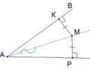
Let's construct a plane and m.A, not belonging to the plane. Their t.A draw a straight line, perpendicular to the plane. The point of intersection of a straight line with a plane is designated H. The segment AN is a perpendicular drawn from point A to the plane. T.N - the base of the perpendicular. Let us take in the plane t.M, which does not coincide with H. The segment AM is an oblique line drawn from point A to the plane. M - the base of the inclined. Segment MN - projection of the inclined onto the plane. Perpendicular AH - distance from point A to the plane. Any distance is a part of a perpendicular.
Theorem about 3 perpendiculars:
A straight line drawn in a plane through the base of an inclined plane perpendicular to its projection onto this plane is also perpendicular to the inclined one itself.
ANGLE BETWEEN A RIGHT AND A PLANE
The angle between the line and the plane is the angle between this line and its projection on the plane.
DIHEDRAL ANGLE. ANGLE BETWEEN PLANES
dihedral angle naz the figure formed by a straight line and 2 half-planes with a common boundary a does not belong to the same plane.
border a- dihedral edge. Half planes - faces of a dihedral angle. To measure dihedral angle. You need to build a linear angle inside it. We mark some point on the edge of the dihedral angle and draw a ray from this point in each face, perpendicular to the edge. The angle formed by these rays linear gl of the dihedral angle. There can be infinitely many of them inside the dihedral angle. They all have the same size.
PERPENDICULARITY OF TWO PLANES
Two intersecting planes perpendicular, if the angle between them is 90.
Feature:
If 1 of 2 planes passes through a line perpendicular to another plane, then such planes are perpendicular.
POLYHEDRALS
Polyhedron- a surface composed of polygons and limiting some geometric body. Facets are the polygons that make up the polyhedra. Ribs- the sides of the edges. Peaks- the ends of the ribs. Polyhedron diagonal back a segment connecting 2 vertices that do not belong to 1 face. A plane on both sides of which there are points of a polyhedron, called . cutting plane. The common part of the polyhedron and the secant area is called section of a polyhedron. Polyhedra are convex and concave. Naz polyhedron convex, if it is located on one side of the plane of each of its faces (tetrahedron, parallelepiped, octahedron). In a convex polyhedron, the sum of all plane angles at each of its vertices is less than 360.
PRISM
A polyhedron composed of 2 equal polygons located in parallel planes and n - parallelograms called prism.
Polygons A1A2..A(p) and B1B2..B(p) - prism bases. А1А2В2В1…- parallelograms, A(p)A1B1B(p) – side edges. Segments A1B1, A2B2..A(p)B(p) – side ribs. Depending on the polygon underlying the prism, the prism naz p-coal. A perpendicular drawn from any point of one base to the plane of another base is called height. If the side edges of the prism are perpendicular to the base, then the prism - straight, and if not perpendicular - then inclined. The height of a straight prism is equal to the length of its lateral edge. Direct prismanaz correct, if its base is regular polygons, all side faces are equal rectangles.
PARALLEPIPED
ABCD//A1B1C1D1, AA1//BB1//SS1//DD1, AA1=BB1=SS1=DD1 (according to the property of parallel planes)
The parallelepiped consists of 6 parallelograms. Parallelograms naz faces. ABSD and A1V1S1D1 - bases, the remaining faces are called side. Points A B C D A1 B1 C1 D1 - tops. Segments connecting vertices ribs. AA1, BB1, SS1, DD1 - side ribs.
Diagonal of a parallelepiped back a segment connecting 2 vertices that do not belong to 1 face.
Saints
1. Opposite faces of a parallelepiped are parallel and equal. 2. The diagonals of the parallelepiped intersect at one point and bisect this point.
PYRAMID
Consider a polygon A1A2..A(n), a point P not lying in the plane of this polygon. Let's connect the point P with the vertices of the polygon and get n triangles: PA1A2, PA2A3….RA(p)A1.
A polyhedron composed of an n-gon and n-triangles over the pyramid. Polygon - base. Triangles - side edges. R - top of the pyramid. Segments А1Р, А2Р..А(p)Р – side ribs. Depending on the polygon lying at the base, the pyramid is called p-coal. The height of the pyramid back a perpendicular drawn from the vertex to the plane of the base. Pyramid called correct, if its base is a regular polygon and the height is at the center of the base. Apothem is the height of the lateral face of a regular pyramid.
TRUNCATED PYRAMID
Consider the pyramid PA1A2A3A(n). draw a cutting plane parallel to the base. This plane divides our pyramid into 2 parts: the upper one is a pyramid similar to this one, the lower one is a truncated pyramid. The side surface consists of a trapezium. Lateral ribs connect the tops of the bases.
Theorem: the area of the lateral surface of a regular truncated pyramid is equal to the product of half the sum of the perimeters of the bases and the apothem.
REGULAR POLYTOPES
A convex polyhedron is called regular, if all its faces are equal regular polygons and the same number of edges converge at each of its vertices. An example of a regular polyhedron is a cube. All its faces are equal squares, and 3 edges converge at each vertex.
regular tetrahedron composed of 4 equilateral triangles. Each vertex is a vertex of 3 triangles. The sum of the flat angles at each vertex is 180.
Regular octahedron Consist of 8 equilateral triangles. Each vertex is a vertex of 4 triangles. Sum of plane angles at each vertex =240
Regular icosahedron Consist of 20 equilateral triangles. Each vertex is a vertex 5 triangle. The sum of flat angles at each vertex is 300.
Cube composed of 6 squares. Each vertex is a vertex of 3 squares. The sum of flat angles at each vertex =270.
Regular dodecahedron Consist of 12 regular pentagons. Each vertex is a vertex of 3 regular pentagons. The sum of flat angles at each vertex = 324.
There are no other types of regular polyhedra.
CYLINDER
A body bounded by a cylindrical surface and two circles with boundaries L and L1 called cylinder. Circles L and L1 back the bases of the cylinder. Segments MM1, AA1 - generators. Forming the composition of the cylindrical or lateral surface of the cylinder. Straight line, connecting the centers of the bases O and O1 naz axis of the cylinder. Generating length - cylinder height. The base radius (r) is the radius of the cylinder.
Cylinder sections
Axial passes through the axis and base diameter
Perpendicular to axis
A cylinder is a body of revolution. It is obtained by rotating a rectangle around 1 of the sides.
CONE
Let us consider a circle (o;r) and a straight line OP perpendicular to the plane of this circle. Through each point of the circle L and t.P we draw segments, there are infinitely many of them. They form a conical surface and generators.
R- vertex, OR - conical surface axis.
Body bounded by a conical surface and a circle with boundary L naz cone. A circle - the base of the cone. Vertex of a conical surface is the apex of the cone. Forming a conical surface - forming a cone. Conical surface - lateral surface of the cone. RO - cone axis. Distance from R to O - cone height. A cone is a body of revolution. It is obtained by rotating a right triangle around the leg.
Cone section
Axial section
Section perpendicular to the axis
SPHERE AND BALL
sphere called a surface consisting of all points in space located at a given distance from a given point. This point is the center of the sphere. This distance is sphere radius.
A line segment connecting two points on a sphere and passing through its center naz the diameter of the sphere.
A body bounded by a sphere ball. Center, radius and diameter of the sphere center, radius and diameter of the sphere.
Sphere and ball are bodies of revolution. Sphere is obtained by rotating a semicircle around the diameter, and ball obtained by rotating a semicircle around the diameter.
in a rectangular coordinate system, the equation of a sphere of radius R with center C(x(0), y(0), Z(0) has the form (x-x(0))(2)+(y-y(0))(2 )+(zz(0))(2)= R(2)