Synthesis of cam mechanisms. Calculation of cam mechanisms Phases of operation of cam mechanisms. Phase and design angles
5.1 General concepts
The mechanism, which includes a rotating link with a working surface of variable curvature, called cam, and the output link in the form of a pusher (oscillator), forming a higher kinematic pair, is called cam.
Classification of flat cam mechanisms and the main parameters of the cam.
Flat cam mechanisms (Fig. 5.1) with a rotating cam are divided into two groups: the 1st group converts the rotational movement of the cam into the translational movement of the pusher; 2nd group - the rotational movement of the cam into the oscillatory movement of the oscillator.
Each of these groups, according to the shape of the element of the driven link, is divided into three more subgroups in which the cam works: a) along the tip; b) by video; c) flat. Cam mechanisms that convert rotational motion into translational, in which the cam operates along a tip or along a roller, are in turn divided into central and deaxial. Central are called those in which the axis of the pusher passes through the center of rotation of the cam. AT deaxial in the same mechanisms, the axis of the pusher is shifted relative to the center of rotation of the cam by a certain amount e called desaxial. There are eight basic cam patterns.
Profile cam is called a curve obtained in the section of the cam element by a plane perpendicular to its axis of rotation. Despite the wide variety of cam profiles, they all have some common parameters.
On fig. 5.2 shows a cam whose profile is drawn by four arcs of circles.

Arc ab drawn from the center O 1, arc bc- from the center of O 2, arc cd- from the center O 1, arc da- from the center O 2 / . The main dimensions of the cam include the following.
Minimum jaw radius R 0- radius connecting the center of rotation of the cam with the nearest point of the cam profile.
Maximum jaw radius R max is the radius connecting the center of the cam to the outermost point of the cam profile.
Pusher lift h- the difference between the lengths of the maximum and minimum cam radii.
Non-working cam angle (non-working phase) φ 0- the central angle based on the arc ab minimum radius. When sliding along an arc of minimum radius, the pusher is stationary and is in the lower position.
Removal angle (removal phase) φ Y bc, connecting the extreme points of the arcs of the minimum and maximum cam radii. When sliding along an arc bc the pusher starts to move and moves to the maximum distance (passes from the lower to the upper position).
Far standing angle (far standing phase) φ d- the central angle of the cam, based on the arc cd maximum radius. While the pusher slides in an arc cd, it is stationary and is located at the maximum distance from the center of rotation of the cam.
Return angle (return phase) φ B- the central angle of the cam, based on the arc da, connecting the extreme points of the arcs of the maximum and minimum cam radii. When sliding along an arc da the pusher returns from the far to its original (lower) position.
Cam working angle (working phase) φ P- the central angle of the cam, equal to the sum of the angles of removal, distance and return ![]() .
.
The sum of all angles must be equal to 360 0:
The cam profile radii R 2 (R 2 /) are the radii of the arcs corresponding to the removal and return phases, respectively. If the curve corresponding to the removal (or return) phase is not an arc of a circle, then the radius of the cam profile in this case will be variable.
5.2 Analysis and synthesis of cam mechanisms
The task of kinematic analysis is to determine the law of motion, speed and acceleration of the pusher (oscillator) according to the known kinematic scheme of the mechanism and the frequency of rotation of the cam.
The determination of the speeds and accelerations of the pusher (oscillator) is found by graphical differentiation of the law of motion of the output link.
To analyze cam mechanisms with an arbitrary cam profile, reverse motion method, at which the cam is considered to be stationary, and the rack, together with the pusher (oscillator), is given a rotational movement around the cam axis with the angular velocity of the cam, but in the opposite direction. In such a movement, the movement of the pusher (oscillator) relative to the cam will be the same as in the true movement with a fixed rack.
During synthesis, the profile of the cam is found according to the known structural scheme, the main dimensions of the cam and the law of motion of the pusher (oscillator).
5.2.1 Central cam mechanism in which the cam operates on a tappet with a point
Mechanism analysis.
Known: the parameters of the kinematic scheme of the mechanism and the frequency of rotation of the cam (min -1).
To find the movement of the pusher, a kinematic diagram of the mechanism is built (Fig. 5.3, a), for example, on a scale
where is the radius of the minimum cam circle in m;
The radius of the circle in the drawing in mm.

On the radius circle, the working angle is plotted (for example), which is found from the expression
where , - respectively, the time of one revolution and the working time in s.
Cam full rotation time
The working angle is divided into equal parts (in Fig. 5.3 - 18) and radii are drawn through the center O 1 and points 1-18 until they meet the cam profile. Distances 1-1 / , 2-2 / , ... from the circle of minimum radius to the profile of the cam are the displacements of the pusher corresponding to the rotation of the cam by an angle determined by the division number.
To build a graphical dependence in the coordinate system, the scales of the displacement of the pusher and time are selected in the coordinate system
; m/mm (5.4)
S/mm (5.5)
where is the ordinate in mm corresponding to the movement of the pusher in the -th position in m;
Abscissa in mm, corresponding to the time of rotation of the cam to the working angle in With.
In the case when , the scales of the kinematic scheme and the graph are the same. The abscissa axis is divided into equal parts (in this case, 18) and segments 1-1 //, 2-2 //, ..., 18-18 //) are drawn through the division points, expressing the corresponding displacements of the pusher on the appropriate scale (Fig. 5.3b).
Synthesis of the mechanism.
Known: the block diagram of the mechanism, the main size R 0 and the frequency of rotation of the cam, the law of motion of the pusher, given by one of the kinematic graphs (Fig. 5.4, a).
You need to build a cam profile.
Let, as in the case of analysis , and the law of motion be represented by a graph .
 a) b)
a) b)
To solve the problem in scale (5.1), a circle of radius R 0 of the cam is drawn and the working angle is plotted on it, which is divided into n equal parts. Rays are drawn through the division points and the center of the circle. The abscissa of the graph is divided into the same n number of parts and the corresponding values are found on the ordinates, which on a scale express the corresponding positions of the pusher tip on the cam profile. Therefore, if we set aside segments from the circle on the rays, taking into account the scale, and connect these points with a smooth line, we will obtain a cam profile that provides the required mode of movement (Fig. 5.4, b).
5.2.2 De-axial cam mechanism, in which the cam operates on a tappet with a tip
Kinematic analysis of the mechanism.
Let the kinematic scheme of the mechanism (Fig. 5.5) be given on the scale (5.1). We draw a circle of minimum radius and a circle of deaxial (whose radius is equal to deaxial). If, instead of a cam, a circle of minimum radius rotated (around the same center O 1), then the pusher would be stationary, and its tip would constantly be at the point 6 / (and would slide along the circle of minimum radius). In fact, the cam also rotates in the position shown in Fig. 5.5, a, the tip of the pusher is at point 6 // ; therefore, the segment 6 / -6 // of the tangent to the deaxial circle, enclosed between the circle of minimum radius and the profile of the cam, is the rise of the pusher in this position. To find the lifts of the pusher in other positions, it is necessary to break the deaxial circle into parts, draw tangents through the division points and measure the corresponding segments of these tangents. But usually the division does not start from an arbitrary point, but from the point at which the lift of the pusher begins. On fig. 5.5, a it can be seen that such a point on the cam profile is the point O / (at which the cam profile is separated from the circle of minimum radius). We need to find the corresponding point on the circumference of the deaxial. To do this, we draw a tangent to the circle of the deaxial through the point O /. The touch point O will be the desired point. From the point O on the circumference of the deaxial, we set aside the working angle (5.2) and divide it into several equal parts (in Fig. 5.5, a working angle is divided into 8 parts). Through the division points we draw tangents to the circle of the deaxial. The segments of the tangents between the circle of minimum radius and the profile of the cam will be the desired displacement of the pusher (Fig. 5.5, b).
It would be possible to build graphs for these displacements using expressions (5.4) and (5.5).

But, as you can see, not a single tangent passed through the toe of the cam (point), therefore, the graph will not have the maximum lift of the pusher. To correct this situation, draw a tangent to the deaxial circle through the toe of the cam and mark the point of contact.
Postponing the found movements of the pusher on a scale (5.4) from the abscissa axis (Fig. 5.5, b), we get a graph.
Despite the fact that the cam was symmetrical, the graph turned out to be asymmetrical (the asymmetry of the graph can be judged at least by the fact that the maximum lift of the pusher was not in the middle of the graph). This property of deaxial cam mechanisms is used in practice when they want to get a symmetrical cam with an asymmetric schedule.
Synthesis of the mechanism.
Now let the graph be given (Fig. 5.5, b) and the main dimensions of the cam (minimum radius of the cam, deaxial and working angle of the cam). It is required to build a cam profile.
We divide the given graph by ordinates into several equal sections (in Fig. 5.5, b The graph is divided into eight sections). If none of the ordinates passed through the point corresponding to the maximum lift of the pusher, then we draw an additional ordinate through this point.
We select the scale (5.1), in which the kinematic diagram of the mechanism should be drawn, and from one center O 1 (Fig. 5.5, a) we draw two circles: the minimum radius and the deaxial. On the circle of the deaxial from an arbitrary point O, we set aside the working angle (5.2) and divide it into as many equal parts as the graph is divided into. Through division points 0, 1, 2, etc. we draw tangents to the circle of the deaxial. On these tangents from the circle of minimum radius, we postpone the displacements of the pusher, taken from the graph. If the length scales on the graph and the kinematic diagram are different, then, using the dependencies (5.1) and (5.4), we obtain them on the required scale. By connecting the ends of the postponed movements with a smooth curve, we obtain the desired cam profile (Fig. 5.5, a). From the axis of rotation about 1 cam at a distance of deaxial, we draw a pusher. Thus, the required kinematic diagram of the cam mechanism is ready.
5.2.3 Central cam mechanism in which the cam runs on a roller follower
Mechanism analysis.
Let the kinematic scheme of the central cam mechanism be given (Fig. 5.6, a). It is required to perform a kinematic analysis, i.e., plot a graph.
The trajectory of the center of the roller (point B) when it moves relative to the cam (in reverse motion) is called center profile cam. Since the center of roller B is always at the same distance from the actual cam profile, equal to the radius of the roller , then the center and actual cam profiles will be equidistant(equivalent) curves.
 |
Construction of an equidistant curve E to this curve To shown in fig. 5.6, c. Let it be required to the given curve To build an equidistant curve E at a distance equal to . For this, on the curve To select a series of points (at a distance of 3-5 mm from each other) and draw arcs from these points with a radius equal to . The envelope of these arcs E and will be the desired equidistant curve. In a particular case, for a circle, an equidistant curve will be a circle concentric to the given one.
On the mechanism diagram (Fig. 5.6, a), we will build the center profile of the cam (its construction is shown in the section of the center profile according to the method described above).
The center profile has its own (increased) minimum radius. Let's denote it by , then
where is the minimum radius of the cam;
Roller diameter.
Now let's replace the real cam, working on a roller, with a center cam, working on a pusher with a tip (in Fig. 5.6, a this pusher is shown by a dotted line). The kinematic analysis of such a scheme is described above.
Synthesis of the mechanism.
Synthesis is performed in the reverse order of analysis. Let the graph be given (Fig. 5.6, b) and the main dimensions of the cam. It is required to build a cam profile. First, we build the center profile of the cam operating along the tip (when constructing the center profile, the minimum radius is assumed to be ).
Then we pass from the center profile to the real one by constructing an equidistant curve "inside". On the site of the real profile (Fig. 5.6, a) its construction is shown (as an equidistant curve).
5.2.4 Deaxial cam mechanism, in which the cam moves the pusher with a roller
Mechanism analysis.
Let the kinematic scheme of a deaxial cam mechanism with a roller be given (Fig. 5.7). A kinematic analysis is required.
We replace the real cam (working along the roller) with a center profile working along a pusher with a tip (its construction is shown in the section of the center profile as an equidistant curve to the actual cam profile). Then, a kinematic analysis of the center profile of the cam is performed, working on a pusher with a tip.
 |
Synthesis of the mechanism.
Synthesis is performed in the reverse order of analysis. First, according to a given schedule, the center profile of the cam is found (when constructing the center profile, the minimum radius of the cam increases by the value of the radius of the roller).
Then they move from the center profile to the real one by constructing an equidistant curve inward (Fig. 5.7). On the section of the real profile, its construction is shown (as an equidistant curve).
5.2.5 Cam mechanism in which the cam moves a flat follower
Mechanism analysis.
Let the kinematic scheme of the cam mechanism with a flat pusher be given (Fig. 5.8, a). It is required to perform a kinematic analysis, i.e., plot a graph
We draw a circle of minimum radius on a scale (5.1), plot the working angle on this circle and divide it into 12 equal parts. Let's use the reverse motion method. Let the axis of the pusher O 1 V turn by 30 0 in the reversed movement and take the first position O 1 V 1. It is necessary to find the position of the pusher plate, which during operation constantly touches the profile of the cam and remains perpendicular to the axis of the pusher. We move the tangent to the profile of the cam, which is also perpendicular to the axis O 1 B 1 of the pusher in the first position. Distance 1-with 1 from the circle of minimum radius to the pusher plate and will be the movement of the pusher in the first position. In the same way we find the displacement 2-s 2 in the second position and in all subsequent ones (movement of the pusher in Fig. 5.8, a shown in bold lines). Postponing the found displacements from the x-axis (Fig. 5.8, b), we get a graph.
 |
 |
Synthesis of the mechanism.
Synthesis is carried out in the reverse order of analysis. Let now the schedule is given (Fig. 5.8, b); it is required to build a cam profile working on a flat pusher. We draw a circle of minimum radius (Fig. 5.8, a). From an arbitrary point About this circle, we postpone the given working angle and divide it into 12 equal parts. According to the graph, we find the displacements of the pusher corresponding to each position of its axis in the inverted motion (breaking the graph into as many equal parts as the operating angle of the cam is divided into). From the circle of minimum radius on the continuation of the radii, we postpone the corresponding displacements taken from the graph, we get points from 1, from 2, from 3, ..., from 12 (if the length scales on the graph and the kinematic diagram are different, then before postponing the displacement of the pusher, you must use formula (5.5) Through the points c 1, c 2, c 3, etc., we draw perpendiculars , , , ... to the extensions of the radii and thus find 12 positions of the plate .
The actual profile of the cam will be the envelope of all positions of the pusher plate. In order to get the cam profile more accurate, it is necessary to find as many positions of the pusher plate as possible in the reversed motion.
5.2.6 Cam mechanism in which the cam moves a rocker with a tip
Mechanism analysis.
Let the kinematic scheme of the cam mechanism with an oscillator be given (Fig. 5.9, a). It is required to perform a kinematic analysis, i.e., plot a graph. The center of rotation of the oscillator O in reverse motion will move along a circle of radius O 1 O (Fig. 5.9, a).
On this circle, from point O, we set aside in the direction opposite to the angular velocity of the cam, the working angle of the cam and divide it into 12 equal parts. On fig. 5.9, a RH oscillator is shown in the lower position (at the beginning of the rise). If on the kinematic diagram the oscillator is shown not in the lower position, but in an intermediate one, then you first need to find the position of the center of rotation of the oscillator corresponding to the beginning of the rise in the reversed motion (to a circle of radius O 1 O), and from this point lay off the working angle. In the reverse motion, the center of rotation O of the oscillator on a circle of radius O 1 O occupies successive positions 1, 2, 3, ..., 12 (corresponding to the rotation of the cam by the same angle). The second end of the oscillator (point B) slides along the profile of the cam. We find the successive positions of point B. To do this, by the length of the oscillator OB from points 1, 2, 3, ..., 12 (circles of radius O 1 O), we make notches on the cam profile, we get points 1 / , 2 / , 3 / , ..., 12 / .
In true motion, the end of the oscillator B will move along an arc described by the radius OB from the center O. To find the corresponding positions of point B in true motion, it is necessary to make notches on the arc from the center of rotation O 1 of the cam with distances O 1 1 /, O 1 2 /, О 1 3 / , …, О 1 12 / , we get points 1 // , 2 // , 3 // , …, 12 // . When constructing a graph, instead of the angles of rotation of the oscillator, it is possible to plot the lengths of the arcs B-1 //, B-2 //, etc., measured directly along the arc. The scaling factor of the oscillator rotation angle in this case
 ,rad/mm, (5.7)
where is the swing angle of the oscillator, deg;
The maximum ordinate on the chart, mm.
 |
Synthesis of the mechanism.
Synthesis is performed in the reverse order of analysis. Now let the graph (Fig. 5.9, b), the minimum radius of the cam and the length of the OB oscillator be given. It is required to build a cam profile.
From an arbitrary point O 1 we describe a circle of minimum radius (Fig. 5.9, a). On this circle, in an arbitrary place, we select point B (corresponding to the beginning of the turn of the oscillator). From point B in a given direction (and if the direction is not set, then in an arbitrary direction), we set aside the length of the oscillator VO. Then, from the center O 1, we describe a circle with a radius O 1 O. If the center distance O 1 O is specified, and not the length of the oscillator VO, then a circle with this radius is immediately described and an arbitrary point O is selected on it, corresponding to the position of the oscillator at the beginning of the rise. On this circle, from the point O, we set aside (in the direction opposite to the angular velocity of the cam) the working angle and divide it into several equal parts. Then, from the center O with radius OB, we draw an arc and plot on it (on the required scale) the angular displacements of the oscillator, taken from the given graph. The points belonging to the profile of the cam are obtained by serifs.
To do this, from the center O 1 with radii equal to the distances O 1 1 //, O 1 2 //, O 1 3 //, etc., we draw arcs on which we make notches with the length of the OB oscillator from points 1, 2, 3 , …, 12, lying on a circle of radius О 1 О. Connecting the points 1 / , 2 / , 3 / , …, 12 / (arc intersections) with a smooth curve, we obtain the actual cam profile.
5.2.7 Cam mechanism in which the cam moves a rocker with a roller
Mechanism analysis.
Let the kinematic scheme of the cam mechanism with a roller oscillator be given (Fig. 5.10). A kinematic analysis is required. We replace the real cam operating along the roller with a center profile operating along an oscillator with a tip (its construction as an equidistant curve is shown in the section of the center profile). Then we perform a kinematic analysis of the center profile of the cam operating on a vibrator with a tip (in Fig. 5.10 such an oscillator is shown by a dotted line).
 |
Synthesis of the mechanism.
Synthesis is performed in the reverse order of analysis. First, according to a given schedule, the center profile of the cam is found (when constructing the center profile, the minimum radius of the cam is increased by the value of the radius of the roller).
Then they pass from the center profile to the real one by constructing an equidistant curve inward (on the section of the real profile, its construction as an equidistant curve is shown).
5.2.8 Cam mechanism in which the cam operates on a plane oscillator
Mechanism analysis.
Let the kinematic scheme of the cam mechanism with a flat oscillator be given (Fig. 5.11, a). It is required to perform a kinematic analysis, i.e., plot a graph.
The center of rotation O of the oscillator in reverse motion will move along a circle of radius O 1 O (Fig. 5.11, a). On this circle from the point O, corresponding to the lower position (the beginning of the rise) of the oscillator, we set aside the working angle in the direction opposite to the angular velocity of the cam and divide it into 12 equal parts. In the reverse movement, the center of rotation O of the oscillator occupies successive positions on the circle O 1 O, designated 1, 2, 3, ..., 12, corresponding to the rotation of the cam by the same angle (by 30 0).
Having drawn from points 1, 2, 3, etc. (circles of radius O 1 O) tangents to the profile of the cam, we find the successive positions of the oscillator in reverse motion, corresponding to the rotation of the cam through the same angle. Putting the length of the oscillator OA on these tangents, we get the points 1 / , 2 / , 3 / , ..., which are successive positions of the free end A of the oscillator in reverse motion. If none of the positions of the oscillator touches the most distant point of the cam profile, then through this point we draw an additional tangent, (Fig. 5.11, a), corresponding to the maximum rotation of the oscillator.
In true motion, when the oscillator rotates, its free end (point A) moves along an arc of a circle of radius OA. In order to find successive positions of the free end of the oscillator on the arc, it is necessary to make notches from the center of rotation O 1 of the cam with distances equal to O 1 1 / , O 1 2 / , O 1 3 / , ...; we get points 1 // , 2 // , 3 // , … If these points are connected to the center of rotation O of the oscillator, then we will obtain successive positions of the oscillator corresponding to the rotation of the cam by the same angle (by 30 0).
And the center distance O 1 O (Fig. 5.11, a). On a circle of radius O 1 O, we select the center of rotation of the oscillator O in an arbitrary place, set it aside from it (in the direction opposite to the angular velocity, we get the first position of the oscillator by connecting points 2 and - the second position of the oscillator, etc. The actual cam profile will be the envelope of all oscillator positions.
In order for the cam profile to be more accurate, it is necessary to find as many positions of the oscillator as possible.
Cam design
Summary: Cam mechanisms. Purpose and scope. The choice of the law of motion of the pusher of the cam mechanism. Classification of cam mechanisms. Main parameters. Geometric interpretation of the analogue of velocity. Influence of the pressure angle on the operation of the cam mechanism. Synthesis of the cam mechanism. Stages of synthesis. Selection of the radius of the roller (rounding of the working section of the pusher).
Cam mechanisms
The working process of many machines makes it necessary to have mechanisms in their composition, the movement of the output links of which must be carried out strictly according to a given law and coordinated with the movement of other mechanisms. The most simple, reliable and compact to perform such a task are cam mechanisms.
Kulachkov is called a three-link mechanism with a higher kinematic pair whose input link is called cam, and the output pusher(or rocker).
cam is called the link to which the element of the higher kinematic pair belongs, made in the form of a surface of variable curvature.
A rectilinearly moving output link is called pusher, and rotating (swinging) - rocker.
Often, in order to replace sliding friction with rolling friction in the highest pair and reduce wear, both the cam and the pusher, an additional link is included in the mechanism diagram - a roller and a rotational kinematic pair. The mobility in this kinematic pair does not change the transfer functions of the mechanism and is a local mobility.
They reproduce the movement of the output link - pusher theoretically exactly. The law of motion of the pusher, given by the transfer function, is determined by the profile of the cam and is the main characteristic of the cam mechanism, on which its functional properties, as well as dynamic and vibrational qualities, depend. The design of the cam mechanism is divided into a number of stages: the assignment of the law of motion of the pusher, the choice of a block diagram, the determination of the main and overall dimensions, the calculation of the coordinates of the cam profile.
Purpose and scope
Cam mechanisms are designed to convert the rotational or translational motion of the cam into a reciprocating rotational or reciprocating motion of the pusher. An important advantage of cam mechanisms is the ability to provide accurate dwells of the output link. This advantage determined their wide application in the simplest cyclic automatic devices and in mechanical calculating devices (arithmometers, calendar mechanisms). Cam mechanisms can be divided into two groups. The mechanisms of the first ensure the movement of the pusher according to a given law of motion. The mechanisms of the second group provide only the specified maximum displacement of the output link - the stroke of the pusher. In this case, the law by which this movement is carried out is selected from a set of typical laws of motion, depending on the operating conditions and manufacturing technology.
The choice of the law of motion of the pusher of the cam mechanism
The law of motion of the pusher called the displacement function (linear or angular) of the pusher, as well as one of its derivatives, taken in time or a generalized coordinate - the displacement of the leading link - the cam. When designing a cam mechanism from a dynamic point of view, it is advisable to proceed from the law of change in the acceleration of the pusher, since it is the accelerations that determine the inertia forces that arise during the operation of the mechanism.
There are three groups of laws of motion, characterized by the following features:
1. the movement of the pusher is accompanied by hard blows,
2. the movement of the pusher is accompanied by soft impacts,
3. The movement of the pusher occurs without shock.
Very often, according to the conditions of production, it is necessary to move the pusher at a constant speed. When applying such a law of motion of the pusher in the place of an abrupt change in speed, the acceleration theoretically reaches infinity, and the dynamic loads must also be infinitely large. In practice, due to the elasticity of the links, an infinitely large dynamic load is not obtained, but its magnitude is still very large. Such impacts are called "hard" and are allowed only in low-speed mechanisms and with small weights of the pusher.
Soft impacts are accompanied by the operation of the cam mechanism if the speed function does not have a discontinuity, but the acceleration function (or an analog of acceleration) of the pusher undergoes a discontinuity. An instantaneous change in acceleration by a finite amount causes a sharp change in dynamic forces, which also manifests itself in the form of a shock. However, these attacks are less dangerous.
The cam mechanism operates smoothly, without shocks, if the functions of the speed and acceleration of the pusher do not undergo a break, change smoothly and provided that the speeds and accelerations at the beginning and at the end of the movement are equal to zero.
The law of pusher motion can be specified both in analytical form - in the form of an equation, and in graphical form - in the form of a diagram. In assignments for a course project, the following laws of change in analogs of accelerations of the center of the pusher roller are found, given in the form of diagrams:
The uniformly accelerated law of change of the analog of the pusher acceleration, with the uniformly accelerated law of the pusher movement, the designed cam mechanism will experience soft shocks at the beginning and at the end of each of the intervals.
The triangular law of change of the analogue of acceleration ensures the shockless operation of the cam mechanism.
The trapezoidal law of change of the analogue of acceleration also ensures the shock-free operation of the mechanism.
Sinusoidal law of change of analog of acceleration. Provides the greatest smoothness of movement (characteristic is that not only speed and acceleration, but also derivatives of a higher order change smoothly). However, for this law of motion, the maximum acceleration at the same phase angles and the stroke of the pusher is greater than in the case of uniformly accelerated and trapezoidal laws of change in analogues of accelerations. The disadvantage of this law of motion is that the increase in speed at the beginning of the rise, and, consequently, the rise itself is slow.
The cosinusoidal law of change of the analogue of acceleration causes soft shocks at the beginning and at the end of the pusher stroke. However, with the cosine law, there is a rapid increase in speed at the beginning of the stroke and its rapid decrease at the end, which is desirable when many cam mechanisms are operating.
From the point of view of dynamic loads, shockless laws are desirable. However, cams with such laws of motion are technologically more complex, since they require more accurate and sophisticated equipment, so their manufacture is much more expensive. The laws with hard impacts have a very limited application and are used in non-critical mechanisms at low speeds and low durability. Cams with shockless laws are advisable to use in mechanisms with high speeds of movement with stringent requirements for accuracy and durability. The most widespread are the laws of motion with soft impacts, with the help of which it is possible to provide a rational combination of the cost of manufacture and the operational characteristics of the mechanism.
Advantages of cam mechanisms
All mechanisms with VKP are low-link, therefore, they make it possible to reduce the dimensions of the machine as a whole.
Ease of synthesis and design.
Mechanisms with VKP reproduce the transfer function more accurately.
Provide a wide variety of laws of motion of the output link.
Mechanisms with VKP must have a power or geometric closure.
The contact forces in the HCP are much higher than in the LCP, which leads to wear, i.e. 2 profiles lose their shape and, as a result, their main advantage.
The complexity of processing the profile of the cam.
The impossibility of working at high speeds and transmitting high powers.
The main parameters of the cam mechanism
The profile of the cam can be composed of arcs of two concentric circles and curves that make the transition from one circle to another.
Most cam mechanisms are cyclic mechanisms with an equal cycle period. When the cam rotates, the pusher performs reciprocating or reciprocating rotational movements with a stop in the upper and lower positions. Thus, in the cycle of movement of the pusher, in the general case, four phases can be distinguished: removal, distant standing (or standing), approach and close standing. Accordingly, the cam angles or phase angles are divided into:
Removal (lifting) angle
Angle of far (upper) stand
Angle of approach (descent)
The angle of the near (lower) stand.
The sum of three angles forms an angle called the working angle.
In particular cases, there may be no corners of the upper and lower rise, then.
The mechanism cam is characterized by two profiles:
Center (or theoretical)
Constructive (or working).
Under constructive refers to the outer working profile of the cam.
Theoretical or center a profile is called, which in the cam coordinate system describes the center of the roller (or rounding of the working profile of the pusher) when the roller moves along the constructive profile of the cam.
phase is called the angle of rotation of the cam.
profile angle is called the angular coordinate of the current working point of the theoretical profile, corresponding to the current phase angle. In general, the phase angle is not equal to the profile angle.
The movement of the pusher and the angle of rotation of the cam are counted from the beginning of the lifting phase, i.e. from the lowest position of the center of the roller, which is at a distance from the center of rotation of the cam. This distance is called initial radius or the radius of the zero initial washer and coincides with the minimum radius vector of the cam center profile.
The maximum displacement of the output link is called pusher stroke.
Pusher out-of-axis - eccentricity - for cams with a translational-moving pusher.
Center distance - the distance between the center of rotation of the cam and the fixed point of the rocker - for cams with a rocker pusher.
The pressure angle is the angle between the velocity at the point of contact and the normal to the profile (i.e. the direction of the force). Usually this angle is denoted or. And at one point of contact, two profiles have a different pressure angle.
Without friction, the force is directed along the common normal at the point of contact of the profiles. Thus, in a cam mechanism, the pressure angle is the angle between the normal to the center profile of the cam and the speed of the roller center.
The dimensions of the cam mechanism are determined from kinematic, dynamic and structural conditions.
- Kinematic conditions - ensuring the reproduction of a given law of motion of the pusher.
- Dynamic - ensuring high efficiency and no jamming.
- Structural - ensuring the minimum size of the mechanism, strength and wear resistance.
Geometric interpretation of pusher speed analog
Cam and pusher form VKP. The pusher moves forward, therefore, its speed is parallel to the guide. The cam performs a rotational movement, so its speed is directed perpendicular to the radius of rotation at the current point and the relative sliding speed of the profiles is directed along a common tangent to them.
where, a is the engagement pole in the VKP, which is located at the intersection of the normal to the profiles at the point of contact with the line of centers. Because the pusher moves forward, then its center of rotation lies at infinity, and the line of centers passes perpendicular to the velocity through the center of the cam.
The velocity triangle and are similar as triangles with mutually perpendicular sides, i.e. the ratio of the corresponding sides is constant and equal to the similarity coefficient: , whence.
Those. the analog of the pusher speed is represented by a segment perpendicular to the pusher speed, which is cut off by a straight line parallel to the contact normal and passing through the center of the cam.
Synthesis formulation: If, on the continuation of a beam drawn from the center of the roller perpendicular to the speed of the pusher, a segment of length is set aside from the point and a straight line parallel to the contact normal is drawn through the end of this segment, then this straight line will pass through the center of rotation of the leading link (cam) point.
Thus, in order to get a segment depicting an analogue of the speed of the pusher, it is necessary to turn the speed vector of the pusher on in the direction of rotation of the cam.
Influence of the pressure angle on the operation of the cam mechanism
Reducing the initial radius of the Cam, other things being equal, leads to an increase in pressure angles. With an increase in pressure angles, the forces acting on the links of the mechanism increase, the efficiency of the mechanism decreases, and the possibility of self-braking (jamming of the mechanism) arises, i.e. no force from the side of the leading link (cam) can move the driven (pusher) from its place. Therefore, to ensure reliable operation of the cam mechanism, it is necessary to choose its main dimensions in such a way that the pressure angle in any of the positions does not exceed a certain allowable value.
When determining the main dimensions of the cam mechanism with a rocker pusher, it is sufficient that the pressure angle in any of the positions of the mechanism does not exceed
Synthesis of the cam mechanism. Stages of synthesis
In the synthesis of a cam mechanism, as in the synthesis of any mechanism, a number of tasks are solved, of which two are considered in the TMM course: the choice of a block diagram and the determination of the main dimensions of the mechanism links (including the profile of the cam).
The first stage of synthesis is structural. The block diagram determines the number of links in the mechanism; number, type and mobility of kinematic pairs; the number of redundant connections and local mobility. In structural synthesis, it is necessary to substantiate the introduction of the mechanism of each excess bond and local mobility into the scheme. The determining conditions for choosing a block diagram are: a given type of motion transformation, the location of the axes of the input and output links. The input motion in the mechanism is converted into output, for example, rotational to rotational, rotational to translational, etc. If the axes are parallel, then a flat mechanism scheme is selected. With intersecting or crossing axes, a spatial scheme must be used. In kinematic mechanisms, the loads are small, so pushers with a pointed tip can be used. In power mechanisms, to increase durability and reduce wear, a roller is introduced into the mechanism circuit or the reduced radius of curvature of the contact surfaces of the upper pair is increased.
The second stage of synthesis is metric. At this stage, the main dimensions of the links of the mechanism are determined, which provide a given law for the transformation of movement in the mechanism or a given transfer function. As noted above, the transfer function is a purely geometric characteristic of the mechanism, and, therefore, the problem of metric synthesis is a purely geometric problem, independent of time or speed. The main criteria that the designer is guided by when solving problems of metric synthesis are: minimization of dimensions, and, consequently, mass; minimizing the pressure angle in your pair; obtaining a manufacturable form of the cam profile.
Selection of the radius of the roller (rounding of the working area of the pusher)
When choosing the radius of the roller, the following considerations are guided:
The roller is a simple part, the processing of which is not complicated (turned, then heat-treated and polished). Therefore, high contact strength can be ensured on its surface. In the cam, due to the complex configuration of the working surface, this is more difficult to achieve. Therefore, usually the radius of the roller is less than the radius of the initial washer of the structural profile and satisfies the relation, where is the radius of the initial washer of the theoretical profile of the Cam. Compliance with this ratio provides approximately equal contact strength for both the cam and the roller. The roller has a greater contact strength, but since its radius is smaller, it rotates at a higher speed and the working points of its surface participate in a larger number of contacts.
The design profile of the cam must not be pointed or sheared. Therefore, a restriction is imposed on the choice of the roller radius, where is the minimum radius of curvature of the theoretical cam profile.
It is recommended to select a roller radius from a standard range of diameters in the range. In this case, it should be taken into account that an increase in the radius of the roller increases the dimensions and mass of the pusher, worsens the dynamic characteristics of the mechanism (reduces its natural frequency). Reducing the radius of the roller increases the dimensions of the cam and its mass; the speed of the roller increases, its durability decreases.
3.3. Phases of the cam mechanisms. Phase and design angles
Cam mechanisms can implement the laws of motion of almost any complexity at the output link. But any law of motion can be represented by a combination of the following phases:
1. Removal phase. The process of moving an output link (follower or rocker) when the contact point of the cam and the follower moves away from the center of rotation of the cam.
2. Phase of return (approximation). The process of moving the output link as the point of contact between the cam and the follower approaches the center of rotation of the cam.
3. Phases of exposure. The situation when, with a rotating cam, the contact point of the cam and the pusher is stationary. At the same time, they distinguish near dwell phase– when the contact point is at the closest position to the center of the cam, long-range phase– when the point of contact is at its furthest position from the center of the cam and phases of intermediate dwells. The dwell phases take place when the point of contact moves along the section of the profile of the Cam, which has the form of an arc of a circle drawn from the center of rotation of the Cam.
The above classification of phases primarily refers to positional mechanisms.
Each phase of work corresponds to its own phase angle of the mechanism and the design angle of the cam.
The phase angle is the angle through which the cam must turn in order to complete the corresponding phase of operation. These angles are denoted by the letter with an index indicating the type of phase, for example, Y is the phase angle of removal, D is the phase angle of far dwell, B is the phase angle of return, B is the phase angle of near dwell.
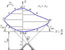
The design angles of the cam determine its profile. They are denoted by the letter with the same indices. On fig. 3.2a shows these angles. They are limited by rays drawn from the center of rotation of the cam to the points on its center profile, where the cam profile changes during the transition from one phase to another.
At first glance, it may seem that the phase and design angles are equal. Let us show that this is not always the case. To do this, we perform the construction shown in Fig. 3.2b. Here, the mechanism with the pusher, if it has an eccentricity, is set to the position corresponding to the beginning of the removal phase; to- the point of contact between the cam and the pusher. Dot to' is the position of the point to, corresponding to the end of the removal phase. It can be seen from the construction that in order for the point to took a position to’ the cam must rotate through an angle Y, not equal to Y, but different by an angle e, called the angle of eccentricity. For mechanisms with a pusher, the following relations can be written:
Y \u003d Y + e, B \u003d B - e,
D = D, B = B
3.4. Choice of the law of motion of the output link
The method for choosing the law of motion of the output link depends on the purpose of the mechanism. As already noted, according to their purpose, cam mechanisms are divided into two categories: positional and functional.

3.4.1. Positional mechanisms
For clarity, let's consider the simplest case of a two-position mechanism, which simply “transfers” the output link from one extreme position to another and back.
On fig. 3.3 shows the law of motion - a graph of the movement of the pusher of such a mechanism, when the entire process of work is represented by a combination of four vases: removal, far rest, return and near rest. Here is the angle of rotation of the cam, and the corresponding phase angles are denoted: y, d, c, b. The displacement of the output link is plotted along the ordinate axis: for mechanisms with a rocker arm, this is - the angle of its rotation, for mechanisms with a pusher S - the displacement of the pusher. 
In this case, the choice of the law of motion consists in determining the nature of the motion of the output link in the phases of removal and return. On fig. 3.3 for these sections some kind of curve is shown, but it is precisely this curve that must be determined. What criteria are laid down as the basis for solving this problem?
Let's go from the opposite. Let's try to do it "simple". Let us set a linear law of displacement in the areas of removal and return. On fig. 3.4 shows what this will lead to. Differentiating the function () or S() twice, we get that theoretically infinite, i.e. unpredictable accelerations and, consequently, inertial loads. This unacceptable phenomenon is called a hard phase shock.
To avoid this, the choice of the law of motion is made on the basis of the acceleration graph of the output link. On fig. 3.5 is an example. Given the desired shape of the acceleration graph and its integration, the functions of speed and displacement are found. 
The dependence of the acceleration of the output link in the phases of removal and return is usually chosen to be shockless, i.e. as a continuous function without acceleration jumps. But sometimes for low-speed mechanisms, in order to reduce the dimensions, the phenomenon is allowed soft hit, when jumps are observed on the acceleration graph, but by a finite, predictable amount.
On fig. 3.6 shows examples of the most commonly used types of laws of change in acceleration. The functions are shown for the delete phase, they are similar in the return phase, but mirrored. On fig. 3.6 presents symmetrical laws when 1 = 2 and the nature of the curves in these sections is the same. If necessary, asymmetric laws are also applied, when 1 2 or the nature of the curves in these sections is different, or both.
The choice of a specific type depends on the operating conditions of the mechanism, for example, law 3.6e is used when a section with a constant speed of the output link is needed in the removal (return) phase.
As a rule, the functions of the laws of acceleration have analytical expressions, in particular, 3.6, a, e - segments of a sinusoid, 3.6, b, c, g - segments of straight lines, 3.6, e - a cosine wave, so their integration in order to obtain speed and displacement is not difficult . However, the amplitude values of the acceleration are not known in advance, but the value of the displacement of the output link during the removal and return phases is known. Let us consider how to find both the acceleration amplitude and all the functions that characterize the motion of the output link.
At a constant angular velocity of rotation of the cam, when the angle of its rotation and time are related by the expression = t functions can be considered both from time and from the angle of rotation. We will consider them in time and in relation to a mechanism with a rocker arm.
At the initial stage, we set the form of the acceleration graph in the form of a normalized, that is, with a unit amplitude, function *( t). For the dependence in Fig. 3.6a it will be *( t) = sin(2 t/T), where Т is the time for the mechanism to pass through the removal or return phase. Real acceleration of the output link:
2 (t) = m *(t), (3.1) 
where m is the currently unknown amplitude.
Integrating expression (3.1) twice, we obtain:
![]()
![]()
Integration is performed with initial conditions: for the removal phase 2 ( t) = 0, 2 ( t) = 0; for the return phase 2 ( t) = 0, 2 ( t) = m . The required maximum displacement of the output link m is known, therefore, the acceleration amplitude
Each value of functions 2 ( t), 2 ( t), 2 (t) can be assigned to the values 2 (), 2 (), 2 (), which are used to design the mechanism, as described below.
It should be noted that there is another reason for the occurrence of shocks in cam mechanisms, associated with the dynamics of their work. The cam can also be designed to be shockless, in the sense that we put into this concept above. But at high speeds, for mechanisms with a power circuit, the pusher (rocker arm) can be separated from the cam. After some time, the closing force restores contact, but this restoration occurs with a blow. Such phenomena can occur, for example, when the return phase is set too small. The cam profile then turns out to be steep in this phase and at the end of the long-range dwell phase, the closing force does not have time to provide contact and the pusher, as it were, breaks off the cam profile at the far end of the stage and can even immediately hit some point of the cam at the near end. For positive locking mechanisms, the roller moves along a groove in the cam. Since there is necessarily a gap between the roller and the walls of the groove, during operation the roller hits the walls, the intensity of these impacts also increases with the speed of rotation of the cam. To study these phenomena, it is necessary to make a mathematical model of the entire mechanism, but these issues are beyond the scope of this course.
| " |
Cam mechanism- this is a mechanism with a higher kinematic pair, which has the ability to provide outage of the output link, and the structure contains at least one link with a working surface of variable curvature.
Cam mechanisms are designed to convert the movement of the leading link into the required type of movement of the output link according to a given law.
The diagram of a typical cam mechanism has a structure containing a rack and two moving links ( fig. 9.1). At the same time, in a cam mechanism with two moving links, it is possible to implement the transformation of movement and force factors according to the law of any complexity.
Rice. 9.1. Kinematic diagrams of cam mechanisms
In typical diagrams of cam mechanisms, the drive link is called cam, and the pusher acts as the output link (Fig. 9.1, but)
or rocker (Fig. 9.1, b).
The cam is a link of the cam mechanism with a working surface of variable curvature.
The pusher is the output link of the cam mechanism that performs translational movements.
The rocker arm is the output link of the cam mechanism, which performs only rotational movements and does not have the ability to rotate through an angle of more than 360 °.
In cam mechanisms, the transformation of movement and force factors is carried out by direct contact of the working surface of the cam with the surface of the output link. In this case, due to the difference in the speeds of movement of the contacting links in the zone of their contact, sliding friction takes place, which leads to intensive wear of these surfaces, as well as to an increase in losses, a decrease in the efficiency and service life of the cam mechanism. To replace sliding friction with rolling friction in the higher kinematic pair, an additional link is introduced into the cam mechanism circuit, which is called a roller. The roller forms a single-moving kinematic pair of the 5th class with the output link (Fig. 9.2). The mobility of this
9. CAM MECHANISMS
kinematic pair does not affect the transfer function of the cam mechanism and is a local mobility.
Rice. 9.2. Kinematic diagrams of cam mechanisms with a roller
When an additional link is introduced into the circuit - a roller - the transformation of movement and force factors is carried out by means of contact of the working surface of the cam with the surface of the roller, which interacts with the output link. In this case, the cam has two types of profiles ( fig. 9.3): constructive and theoretical.
Rice. 9.3. Types of cam profiles in cam mechanisms
Structural (working) profile is the outer profile of the cam. Theoretical ( center) profile is a profile that describes
There is no center of the roller when it rolls without sliding along the structural profile of the cam.
9.1. CLASSIFICATION OF CAM MECHANISMS
Cam mechanisms are classified: 1) according to their official purpose:
cam mechanisms that ensure the movement of the output link according to a given law of motion;
Theory of mechanisms and machines. Proc. allowance |

9. CAM MECHANISMS
9.1.
cam mechanisms that provide only the specified maximum displacement of the output link (stroke of the pusher or swing angle of the rocker arm);
2) according to the arrangement of links in space: flat cam mechanisms ( rice. 9.1, fig. 9.2);
spatial cam mechanisms ( fig. 9.4);
Rice. 9.4. Schemes of spatial cam mechanisms
3) according to the type of cam movement:
cam mechanisms with rotational movement of the cam (fig. 9.2); cam mechanisms with translational movement of the cam (Fig. 9.5); cam mechanisms with helical cam movement;
Rice. 9.5. Schemes of cam mechanisms with translational movement of the cam
4) according to the type of movement of the output link:
cam mechanisms with translational movement of the output
link (Fig. 9.1, but, Fig. 9.2, but, Fig. 9.4, but, Fig. 9.5, but);
cam mechanisms with rotational movement of the output link
(Fig. 9.1, b, Fig. 9.2, b, Fig. 9.4, b, Fig. 9.5, b);
5) by the presence of a video in the scheme:
cam mechanisms with a roller (fig. 9.2, fig. 9.4, fig. 9.5); cam mechanisms c without roller (fig. 9.1);
6) by type of cam:
cam mechanisms with a flat cam (fig. 9.1, fig. 9.2, fig.
9.5 );
cam mechanisms with a cylindrical cam (fig. 9.4); cam mechanisms with a globoid cam (Fig. 9.6, but); cam mechanisms with a spherical cam (Fig. 9.6, b);
Theory of mechanisms and machines. Proc. allowance |

9. CAM MECHANISMS
9.1. Classification of cam mechanisms
Rice. 9.6. Schemes of cam mechanisms with globoid and spherical cams
Rice. 9.7. Diagrams of de-axial cam mechanisms
7) according to the shape of the working surface of the output link:
cam mechanisms with a pointed working surface
leg link (Fig. 9.1, a, Fig. 9.7, b, Fig. 9.8, b);
cam mechanisms with a flat working surface of the output link (Fig. 9.7, but, Fig. 9.8, but);
cam mechanisms with a cylindrical working surface of the output link (fig. 9.2);
cam mechanisms with a spherical working surface of the output link (Fig. 9.7, c, d, Fig. 9.8, c, d);
8) by the presence of displacement:
deaxial cam mechanisms ( fig. 9.7); axial cam mechanisms (fig. 9.8).
Theory of mechanisms and machines. Proc. allowance |

9. CAM MECHANISMS
9.1. Classification of cam mechanisms
Rice. 9.8. Diagrams of axial cam mechanisms
Deaxial cam mechanism is a cam mechanism, in which
the axis of the path of the output link is shifted relative to the center of rotation of the cam by a certain amount (Fig. 9.7). The amount of displacement is called eccentricity, or deaxial, and is denoted e.
Axial cam mechanism- this is a cam mechanism in which the axis of the path of the output link passes through the center of rotation of the cam ( fig. 9.8).
9.2. METHODS FOR CLOSING ELEMENTS OF THE HIGHEST KINEMATIC PAIR
AT During the movement of the cam mechanisms, a situation is possible leading to the loss of contact of the moving links, which leads to the opening of the elements of the higher kinematic pair. The opening of the elements of the higher kinematic pair leads to the termination of its existence, which is reflected in the law of movement of the links in the form of breaks and is unacceptable for the normal operation of the cam mechanisms. To ensure the constancy of contact of the links that form the highest kinematic pair, the following closing methods are used in cam mechanisms:
Power circuit- this is a way to ensure the constancy of contact of the links of the higher kinematic pair by using the gravity forces of the links or the elastic forces of the springs (Fig. 9.9).
AT In cam mechanisms with power closing of the links forming the higher pair, the movement of the output link in the removal phase is carried out due to the action of the contact surface of the cam on the contact surface of the output link, i.e. the cam is the leading link, and the output link is the driven link: pusher or rocker. In the approach phase, the output link moves due to the action of the elastic force of the spring or the gravity force of the output link, i.e. the leading link is the output link: pusher or rocker, and the driven link is the cam.
Theory of mechanisms and machines. Proc. allowance |

9. CAM MECHANISMS
9.2. Methods for closing elements of a higher kinematic pair
Rice. 9.9. Schemes of cam mechanisms with force closure
Geometric closure- this is a way to ensure the constancy of contact of the links of the higher kinematic pair by means of the configuration of the working surfaces of the cam (Fig. 9.10).
Rice. 9.10. Diagrams of positive cam mechanisms
In cam mechanisms with geometrically locking the links that form the higher pair, the movement of the output link in the removal phase is carried out due to the impact of the outer working surface of the cam on the contact surface of the output link. The movement of the output link in the approach phase is a consequence of the impact of the inner working surface of the Cam on the contact surface of the output link. In both phases, the cam acts as the leading link, and the output link is the driven link: pusher or rocker.
Theory of mechanisms and machines. Proc. allowance |
![]()
9. CAM MECHANISMS
9.3. MAIN PARAMETERS OF THE CAM MECHANISM
Cam mechanisms formed on the basis of typical schemes belong to cycloidal mechanisms with a period of operation equal to 2π, and are characterized by the presence of several phases of movement of the output link (Fig. 9.11):
the removal phase is the phase of movement of the cam links by moving the output link from the lower position to the upper one;
upper standing or resting phase
oval mechanisms, accompanied by standing or stand output link in the upper position;
approach phase - this is the phase of movement of the links of the cam mechanisms, accompanied by the movement of the output link from the upper position to the lower;
lower standing or resting phase is the phase of movement of the cam links
oval mechanisms, accompanied by standing or stand output link in the down position.
ϕу |
ϕ c.c. |
ϕс |
ϕ n.v. |
|
ϕ r.x |
ϕ x.x |
|||
Rice. 9.11. Phases of movement of the output link of the cam mechanisms |
||||
Each phase of the movement of the links of the cam mechanisms is characterized by the corresponding two types of angles (Fig. 9.12):
phase angle ϕ is the angle of rotation of the cam during the action of a certain phase of the movement of the output link;
profile angle δ is the angular coordinate of the operating point of the theoretical cam profile corresponding to the current phase angle.
In accordance with the classification of phases, phase angles are divided into four types ( fig. 9.11):
phase angle of removal ϕ y (Fig. 9.12); phase angle of the upper standing or standing ϕ in. in (Fig. 9.12);
Theory of mechanisms and machines. Proc. allowance |

9. CAM MECHANISMS
9.3. The main parameters of the cam mechanism
phase angle of approach ϕ with (Fig. 9.12); phase angle of the lower standing or standing ϕ n.v (Fig. 9.12).
Rice. 9.12. Phase and profile angles of cam mechanisms
The sum of all four phase angles forms the cyclic phase angle:
ϕ = ϕу + ϕv.v + ϕс + ϕн.v = 2 π.
The sum of the first three phase angles is the phase angle of the working stroke of the cam mechanism (Fig. 9.11):
ϕ r.x = ϕ y + ϕ v.v + ϕ s.
The idle phase angle of the cam mechanism is equal to the phase angle of the lower dwell (Fig. 9.11), i.e.
ϕ x.x = ϕ n.v.
Each phase of the movement of the links of the cam mechanisms has its own profile angle, the angles are also divided into four types ( fig. 9.12):
removal angle δ y ; the angle of the upper standing or standing δ in. in; approach angle δ with ;
angle of lower standing or standing δ n.v.
In the general case, the phase and profile angles of the corresponding phases of movement of the links of typical cam mechanisms are not equal to each other:
ϕ ≠ δ.
The equality of the phase and profile angles of the corresponding phases of the movement of the links is characteristic only in the phase of the lower dwell (Fig. 9.12), and for the remaining phases of the movement of the links, it takes place only for typical cam mechanisms without a roller.
Theory of mechanisms and machines. Proc. allowance |

9. CAM MECHANISMS
9.4. STRUCTURAL ANALYSIS OF FLAT CAM MECHANISMS
The links of typical cam mechanisms move in parallel planes, therefore, these mechanisms are flat, the mobility of which is calculated by the Chebyshev formula.
Cam mechanisms without a roller (Fig. 9.1 ). The structure of both types of ti-
new cam mechanisms consists of three links, of which cam 1 and pusher or rocker arm 2 are movable links, and rack 0 is a fixed link, therefore, n = 2. The rack is represented in the scheme of the mechanism with a pusher with one hinged-fixed support and a fixed slider, and in the scheme of mechanisms with a rocker arm - two hinged-fixed supports. The moving links and the rack form two rotational kinematic pairs with a mobility equal to one: 0 - 1, 2 - 0 and one higher kinematic sail mobility equal to two: 1 - 2, therefore, p 1 = 2, p 2 = 1.
W = 3 2 - 2 2 - 1 = 6 - 4 - 1 = 1.
The result means that one generalized coordinate is enough to unambiguously determine the relative position of the links of mechanisms of this type.
Cam mechanisms with a roller (Fig. 9.2 ). The schemes of both cam mechanisms consist of four links, of which cam 1, pusher or rocker arm 2 and roller 3 are movable links, and rack 0 is a fixed link, therefore, n = 3. The rack is presented in the scheme of the mechanism with a pusher of onehinged-fixedsupport and a fixed slider, and in the scheme of mechanisms with a rocker arm - twohinged-fixedsupports. The moving links and the rack form three rotational kinematic pairs with a mobility equal to one: 0 - 1, 2 - 3, 3 - 0 and one higher kinematic pair with a mobility equal to two: 1 - 3, therefore, p1 = 2, p2 = 1.
Substituting the data obtained into the structural formula, we obtain
W = 3 3 - 2 3 - 1 = 9 - 6 - 1 = 2 .
Calculation according to the Chebyshev formula for typical cam mechanisms with a roller shows that the mobility is equal to two. The result indicates the presence of structural defects in the schemes of typical cam mechanisms with a roller, which indicates the presence of two types of mobility for different functional purposes. The mobility of a typical flat cam mechanism with one drive link forming a primary mechanism with a mobility equal to one is equal to one, therefore, the second unit of mobility is accounted for by the local mobility formed by the roller with the output link:
W = 2 =W 0 +W ì =1 +1,
where W 0 , W m - respectively, the main (calculated) and local mobility of the cam mechanism.
Theory of mechanisms and machines. Proc. allowance |

9. CAM MECHANISMS
9.5. KINEMATIC ANALYSIS OF FLAT CAM MECHANISMS
To carry out a kinematic analysis of typical cam mechanisms, it is necessary to know the main dimensions of all its links or the law of motion of the output link.
In the general case, the goal of kinematic analysis of typical cam mechanisms with a given mechanism scheme is to determine the law of motion of the output link, and with known basic dimensions of all links, to determine the law of motion of the output link.
The law of motion of the output link is determined as a function of the angle of rotation of the cam based on the structural features of the cam mechanism and the specified parameters:
S = f(ϕ),
where ϕ is the angle of rotation of the cam.
This functional dependence can be obtained by an analytical or graph-analytical method. The analytical method, as in the analysis of mechanisms of other types, allows obtaining more accurate data, however, the graphical-analytical method is simpler and gives a clear result, which led to its wide use in engineering calculations to obtain a primary idea of the values and patterns of change in the kinematic parameters of cam mechanisms based on the given conditions.
Graph-analytical method kinematic analysis can be carried out by two methods: the method of kinematic diagrams or the method of kinematic plans. The method of plans as applied to the analysis of typical cam mechanisms is based on the use of replacement mechanisms.
Replacement mechanism- this is a mechanism, the structure of which contains only lower kinematic pairs, which, at certain positions of the leading link, have the same displacements, velocities and accelerations for the output link as the corresponding mechanism with the higher pair.
When choosing a replacement mechanism scheme, the main attention is paid to the preservation of the laws of motion of the driving and output links of the cam mechanisms and the mutual arrangement of the axes of these links. Each higher kinematic pair is replaced by two lower pairs, which leads to the appearance of a fictitious link 3 in the structure of the replacement mechanism. Based on the foregoing, taking into account the type of movement performed by the output link, the cam mechanisms schemes are replaced with the corresponding scheme of a typical lever mechanism.
The kinematic analysis of typical lever mechanisms has been discussed above (see Chapter 2).
In most cases, the law of motion of the output link of a typical cam mechanism is given by means of the second derivative of the path with respect to the angle of rotation or with respect to time (acceleration tax). In this case, to directly obtain the law of motion of the output link, the method of kinematic diagrams is used (Fig. 9.13).
Theory of mechanisms and machines. Proc. allowance |

9. CAM MECHANISMS
9.5. Kinematic analysis of planar cam mechanisms
d 2 S |
F(ϕ) |
||||
dϕ 2 |
|||||
dϕ 2 |
|||||
F(ϕ) |
|||||
S = f(ϕ)
2 π ϕ
Rice. 9.13. Kinematic analysis of cam mechanisms by the method of diagrams
The process of determining the law of motion is carried out in the following sequence.
First, based on the given conditions, a diagram of the analogue of the
integrating the diagram of the acceleration analog, first form the diagram
mu analog speed |
(ϕ) (Fig. 9.14, b), then, using the graphic |
|||
diagram integration |
speed analog, get a path diagram |
|||
s \u003d f (ϕ) (Fig. 9.13, c). |
||||
Kinematic analysis allows obtaining the necessary data for the transition to the stage of metric synthesis of cam mechanisms.
9.6. SYNTHESIS OF FLAT CAM MECHANISMS
The main criteria that guide in solving the problems of synthesizing cam mechanisms are: minimization of overall and mass characteristics and values of pressure angles, as well as ensuring the manufacturability of the constructive profile of the cam.
The synthesis of any cam mechanism is carried out in two stages: structural synthesis and metric synthesis.
At the stage of structural synthesis, the formation of a structural diagram of the cam mechanism is carried out, i.e., the number of links is substantiated
Theory of mechanisms and machines. Proc. allowance |

9. CAM MECHANISMS
9.6. Synthesis of flat cam mechanisms
mobile links and types of movement performed by them; number and type of rack elements; number, class and mobility of kinematic pairs, number and type of kinematic chains. In addition, the introduction of each excess connection and local mobility into the structure of the cam mechanism is substantiated. The determining conditions when choosing a block diagram are: the given laws of transformation of the motion of the input and output links and the relative position of the axes of these links. If the axes of the input and output links are parallel, then a flat scheme of the mechanism is selected. With intersecting or crossing axes, a spatial scheme must be used. In cam mechanisms operating under the influence of small force factors, an output link with a pointed working surface is used. In cam mechanisms operating under the action of large force factors, in order to increase durability and reduce wear, a roller is introduced into the structure or the reduced radius of curvature of the contacting surfaces of the links is increased.
At the stage of metric synthesis, the main dimensions of the links of the cam mechanism and the configuration of the working surfaces of the cam profiles are determined, which ensures the implementation of the specified laws of motion and the transfer function or the maximum displacement of the output link.
9.7. LAWS OF MOTION OF THE OUTPUT LINK
If the law of motion of the output link is not specified in the terms of reference for the metric synthesis of the cam mechanism, then it must be independently selected from a set of typical laws of motion, which are divided into three groups:
unstressed laws (Fig. 9.14); laws with hard hits (Fig. 9.15); laws with soft impacts (Fig. 9.16).
The main representatives of the shockless laws of motion of the output links are: sinusoidal (Fig. 9.14, a) and trapezoidal laws of motion (Fig. 9.14, b). Both laws ensure smooth operation of the mechanism, however, they have a significant drawback, which is expressed in a slow increase in the displacement of the output link, accompanied by large values of acceleration.
Theory of mechanisms and machines. Proc. allowance |

9. CAM MECHANISMS
dϕ 2 |
|
d 2 S |
|
dϕ 2 |
|
Rice. 9.14. Unstressed laws of motion of the output link of the cam mechanism
Unstressed laws of motion of the output links are preferable from the point of view of the perception of force factors by the links of the cam mechanisms. The cams, implemented according to the shockless laws of motion, have structural profiles of a more complex configuration, the manufacture of which is technologically difficult, since it requires the use of high-precision equipment, therefore their manufacture is much more expensive. Cam mechanisms with shockless laws of output links should be used at high speeds and stringent requirements for accuracy and durability.
dϕ 2 |
||||
d 2 S |
|
dϕ 2 |
|
Rice. 9.15. Laws of motion of the output link of the cam mechanism with hard impacts
Theory of mechanisms and machines. Proc. allowance |

9. CAM MECHANISMS |
|||
9.7. Laws of motion of the output link |
|||
dϕ 2 |
dϕ 2 |
||
d 2 S |
d 2 S |
||
dϕ 2 |
dϕ 2 |
||
Rice. 9.16. Laws of motion of the output link of the cam mechanism |
|||
with soft strokes |
|||
The main representatives of the laws of motion of output links with hard impacts are: linear (Fig. 9.15, a) and linear with transition curves (Fig. 9.15, b). The laws with hard impacts are characterized by the presence at the beginning and end of the phases of removal and approach of points having acceleration values theoretically equal to infinity, which causes the appearance of inertia forces in the contact zone of the cam mechanism links, also equal to infinity. This phenomenon indicates the occurrence of collision of the working surfaces of the contacting links. Hard impact laws have limited application and are used in non-critical mechanisms operating at low speeds and low durability.
To ensure the quality indicators of the cam mechanism, the laws of motion of the output links with soft impacts are the most preferable. Similar laws include: uniformly accelerated (Fig. 9.16, a), cosine (Fig. 9.16, b), linearly decreasing (Fig. 9.16, c) and linearly increasing (Fig. 9.16, d).
The laws with soft impacts allow for the presence of collision of the working surfaces of the contacting links of the cam mechanism, which occur when the acceleration values of the contact points change momentarily to the final
Theory of mechanisms and machines. Proc. allowance |

9. CAM MECHANISMS
9.7. Laws of motion of the output link
size. Soft hits are less dangerous. The implementation of these laws is carried out in mechanisms operating at low speeds with high durability.
In fact, combined laws are most widespread, i.e., laws of motion formed by functions of the same type or functions of different groups.
9.8. DETERMINING THE RADIUS OF THE ORIGINAL CAM CONTOUR
The overall dimensions of the cam mechanism are determined by the parameters of the initial cam contour. The position of the center of rotation of the cam is aligned with the geometric center of the original contour and must satisfy the condition: the current value of the pressure angle at any point of the structural profile of the cam must not exceed the allowable value. If the cam is flat and rotates, then its initial contour is a circle. In this case, the process of searching for the original contour is reduced to determining its radius.
In most cases, the cam only rotates in one direction, however, when carrying out repairs, it is necessary to be able to reverse the movement of the cam. When the direction of movement changes, the phases of removal and approach are reversed. To determine the area of admissible solutions, i.e., the area of \u200b\u200bthe possible location of the center of rotation
cam, a diagram is constructed S = f d dS ϕ . Graphically, the range of valid
solutions is determined by a family of tangents drawn to the resulting curve at angles of inclination with the corresponding values of the allowable pressure angle (Fig. 9.17, Fig. 9.18).
The choice of the center of rotation of the cam is made only within the region of feasible solutions. In this case, the smallest overall dimensions of the cam mechanism must be ensured. The minimum radius of the original contour R min is obtained by connecting the vertex of the region of feasible solutions of point O with the origin of the coordinate system point 0, i.e. R 0 = R min
(fig. 9.17, fig. 9.18).
The radius of the initial contour of the axial cam mechanisms with a pusher, when the phase angles of removal and approach are equal (Fig. 9.17, but) corresponds to the minimum radius, i.e. R 0 = R min. Determination of the radius of the initial contour of axial cam mechanisms with a pusher with an inequality of phase angles of removal and approach (Fig. 9.17, b) is carried out by connecting the origin of the coordinate system of point 0 with point O 1located in the area of admissible solutions and which is the point of intersection of the path axis with one of tangents, i.e. R 0 = R 1 .
Theory of mechanisms and machines. Proc. allowance |

9. CAM MECHANISMS
9.8.
Rmin |
|||||
Rmin |
|||||
Rice. 9.17. Schemes for determining the radius of the initial contour of cam mechanisms with a pusher
To determine the radius of the initial contour of deaxial cam mechanisms with a pusher, it is necessary to draw two straight lines parallel to the path axis S, offset relative to the path axis by an amount proportional to the eccentricity value (Fig. 9.17). At the intersection of the tangents, limiting the area of feasible solutions, with these straight lines, we find the points O 2 and O 3 . We connect the points O 2 and O 3 with the center of the origin of the coordinate system at point 0. The resulting radii R 2 and R 3 will be slightly larger than the minimum radius of the original contour R min .
For deaxial cam mechanisms with a pusher, if the phase angles of removal and approach are equal (Fig. 9.17, a), the radii R 2 and R 3 will be equal in magnitude. In this case, the radius corresponding to the specified location of the eccentricity (right or left) is taken as the radius of the initial contour. For deaxial cam mechanisms with a pusher, if the phase angles of removal and approach are not equal (Fig. 9.17, b), the radii R 2 and R 3 will not be equal in magnitude. In this case, the radius that has a smaller value is taken as the radius of the original contour. AT
in particular, R 2 > R 3 , i.e. R 0 = R 3 .
In cam mechanisms with a rocker arm, for a given center distance a w, we find the positions of the points O 4 and O 5 at the intersection of an arc with a radius R = a w drawn from point E with tangents (Fig. 9.18, a). Connecting the points O 4 and O 5 with the origin point 0, we get the radii R 4 and R 5 . The radius with the smaller value is taken as the radius of the original contour. In particular, R 4 > R 5 , i.e. R 0 = R 4 .
Theory of mechanisms and machines. Proc. allowance |
![]()
9. CAM MECHANISMS
9.8. Determination of the radius of the initial contour of the cam
Rmin |
Rmin |
||||||
Rice. 9.18. Schemes for determining the radius of the original contour |
|||||||
cam mechanisms with rocker arm |
|||||||
To determine the radius of the initial contour of the cam mechanisms with a rocker at a given angle ϕ 0, we find the positions of the points O 6 and O 7 at the intersection of a straight line drawn through the point E at an angle ϕ 0 , laid off from
axes of the analog of speed d dS ϕ with tangents (Fig. 9.18, b). By connecting the points O 6 and
O 7 with the origin point 0, we get the radii R 6 and R 7 . The radius with the smaller value is taken as the radius of the original contour. In particular, R 6 > R 7 , i.e. R 0 = R 7 .
9.9. SELECT RADIUS ROLL
When choosing the radius of the roller, the following provisions are guided -
1. The roller is a simple part, the manufacturing process of which is not complicated. Therefore, high contact strength can be ensured on its working surface. For the cam, due to the complex configuration of the working surface, ensuring high contact strength is very difficult. In order to ensure a sufficient ratio of contact strengths of the working surfaces of the cam and the roller, when choosing the radius of the roller rroll, the following condition is taken into account:
r roll \u003d 0.4 R 0,
where R 0 is the radius of the original cam contour.
The fulfillment of this ratio provides an approximate equality of the contact strengths of the working surfaces of the cam and roller. Radius ro-
Theory of mechanisms and machines. Proc. allowance |

9. CAM MECHANISMS
9.9. Roller Radius Selection
The cam is much smaller than the radius of the original cam contour, therefore, the roller rotates at a higher angular velocity, and the points of its working surface enter into a much larger number of contacts, which leads to uneven wear of the contact surfaces of the cam and roller. To ensure uniform wear of the working surfaces of the cam and roller, the roller surface must have a greater contact strength.
2. The constructive (working) profile of the cam should not be pointed or cut off (Fig. 9.19, but). Therefore, a restriction is imposed on the choice of the radius of the roller:
r roll = 0.7 ρ min,
where ρ min is the minimum radius of curvature of the theoretical cam profile.
A pointed or cut profile of the cam (fig. 9.19, b) will not allow the roller to roll over its top, which leads to damage to the working surfaces of both links and to loss of cam mechanism performance.
3. The value of the radius of the roller is selected from a standard range of natural integers in the following range:
r roll \u003d (0.35 - 0.45) R 0.
When choosing the roller radius, the following points must be additionally taken into account: an increase in the roller radius value leads to an increase in the dimensions and mass of the output link, which worsens the dynamic characteristics of the cam mechanism and reduces the angular velocity of the roller. A decrease in the roller radius value leads to an increase in the dimensions of the cam and its mass, which causes an increase in the angular velocity of the roller and a decrease in the load capacity and service life of the cam mechanism.
ρmin
Rice. 9.19. Scheme of forming the top of the constructive profile of the Cam
Theory of mechanisms and machines. Proc. allowance |

9. CAM MECHANISMS
9.9. Roller Radius Selection
AT In some cases, the introduction of an additional link (roller) into the structure of the cam mechanism is impossible for a number of reasons. In this case, there is no local mobility that replaces sliding friction with rolling friction, and a very small working area with a curved surface is provided on the output link. The points of the curved section slide along the working surface of the cam, i.e., the wear of the output link surface is more intense. To reduce wear, the working section of the output link is rounded. An increase in the rounding radius does not cause an increase in the dimensions and mass of the output link, however, it leads to a decrease in the dimensions of the structural profile of the cam. Based on this, the radius of curvature of the working surface of the output link can be taken quite large in value.
9.10. SYNTHESIS OF PROFILES OF FLAT ROTARY MOVEMENT cams
De-axial cam mechanisms with a pusher . Building a pro
cam lei is carried out in the following sequence (Fig. 9.20):
1. μ l .
3. From the selected point About in the scale factor of lengths, concentric circles with radii R 0 and e are drawn.
4. To a circle with a radius e a tangent is drawn to the intersection with
circle R 0 , the resulting intersection point is the origin of the path axis S .
7. From each division point, tangents are drawn to a circle with a radius e.
Theory of mechanisms and machines. Proc. allowance |

9. CAM MECHANISMS
9.10.
Rice. 9.20. Synthesis of a deaxial cam mechanism with a pusher
8. From point O, which is the center of a circle with radius R 0 , we draw circles with radii equal to the sum of R 0 and the corresponding displacement of the pusher until it intersects with the tangents to the circle with radius e.
For the synthesis of deaxial cam mechanisms with a pusher and a roller, it is necessary to additionally perform the following:
10. r roll.
Axial cam mechanisms with a pusher . Building a pro
cam lei is carried out in the following sequence ( fig. 9.21):
1. The length scale factor is determinedμ l .
2. An arbitrary point is chosen in the free space O, which is the center of the original cam contour.
3. From the selected point About in the scale factor of lengths, a circle with radius R 0 is drawn.
Theory of mechanisms and machines. Proc. allowance |

9. CAM MECHANISMS
9.10. Synthesis of profiles of flat rotary motion cams
work profile
Theoretical Profile
Rice. 9.21. Synthesis of an axial cam mechanism with a pusher
4. The axis of the path S is aligned with the vertical axis of symmetry of the circumferential
sti with radius R 0 . At the intersection of the path axis S with a circle of radius R 0, we get the origin point 0.
5. From the origin on a circle with a radius R 0 in the direction of rotation of the crank phase angles are plotted, and on the axis of the path in scale
coefficient μ l − displacement of the pusher.
6. Arcs of the original contour corresponding to the phase angles of removal
and approach, we divide into equal parts, the number of which is equal to the number of points included in the phases of removal and approach. We connect the obtained points with a point About, which is the center of rotation of the cam.
7. From point O, which is the center of a circle with radius R 0 , we draw circles with radii equal to the sum of R 0 and the corresponding re-
displacement of the pusher to the intersection of the straight lines connecting the point O
With division points.
8. The obtained points are connected by a smooth curve, forming a theoretical cam profile, which at this stage coincides with the working profile.
For the synthesis of axial cam mechanisms with a pusher and a roller, it is necessary to additionally perform the following:
9. Based on the given conditions, the radius of the roller is determined r roll .
Theory of mechanisms and machines. Proc. allowance |

9. CAM MECHANISMS
9.10. Synthesis of profiles of flat rotary motion cams
10. From arbitrarily chosen points of the theoretical cam profile
we draw circles with radii r rol, simulating the position of the roller as part of the cam mechanism circuit.
11. Having drawn an envelope curve with respect to all positions of the roller, we obtain the working profile of the cam.
Cam mechanisms with rocker arm. The construction of cam profiles is carried out in the following sequence ( rice. 9.22):
1. The length scale factor is determinedμ l .
2. An arbitrary point is chosen in the free space O, which is the center of the original cam contour.
3. From the scheme for determining the radius of the original contour depending on
from the given conditions we transfer triangles 0EO 4 (Fig. 9.18, but) or 0EO 7
(Fig. 9.18, b).
4. From point E with radius R = 0E we draw an arc corresponding to the axis
path S.
5. From the origin on a circle with a radius R 0 in the direction of rotation of the crank phase angles are plotted, and on the axis of the path in scale
coefficient μ l - displacement of the rocker.
6. Arcs of the original contour corresponding to the phase angles of removal
and approach, we divide into equal parts, the number of which is equal to the number of points included in the phases of removal and approach. We connect the obtained points with a point About, which is the center of rotation of the cam.
7. From point O, which is the center of a circle with radius R 0, we draw circles with radii equal to the sum of R 0 and the corresponding displacement of the pusher until they intersect with straight lines connecting point O with division points.
8. The obtained points are connected by a smooth curve, forming a theoretical cam profile, which at this stage coincides with the working profile.
Theory of mechanisms and machines. Proc. allowance |

9. CAM MECHANISMS
9.10. Synthesis of profiles of flat rotary motion cams
Rice. 9.22. Synthesis of a cam mechanism with a rocker arm
For the synthesis of cam mechanisms with a rocker arm and a roller, it is necessary to additionally perform the following:
9. Based on the given conditions, the radius of the roller is determined r roll .
10. From arbitrarily chosen points of the theoretical cam profile
we draw circles with radii r rol, simulating the position of the roller as part of the cam mechanism circuit.
11. Having drawn an envelope curve with respect to all positions of the roller, we obtain the working profile of the cam.
Theory of mechanisms and machines. Proc. allowance |