Polarization microscopy. Polarizing microscope. Hardware and equipment
Polarization microscopy allows you to obtain images of unstained anisotropic structures (for example, collagen fibers, myofibrils or microbial cells). The principle of the method is based on studying an object in light formed by two beams polarized in mutually perpendicular planes.
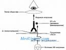
Rice. 11-4. Diagram of a fluorescent microscope.Interference microscopy
Interference microscopy combines the principles of phase-contrast and polarization microscopy. The method is used to obtain a contrasting three-dimensional image of unpainted objects. The principle of the method is based on splitting the light flux in a microscope; one ray passes through the object, the other - past it. Both beams are connected at the eyepiece and interfere with each other.
 Rice. 11-5. Direct immunofluorescence. The direct method involves the use of AT labeled with a fluorescent dye to the Ag of interest; AT interacts with Ag at the sites of their localization, which allows the label to be visualized.
Fluorescence microscopy
Fluorescence microscopy method based on the ability of some substances to glow when exposed to short-wave radiation. In this case, the emitted light waves are longer than the wave that causes the glow. In other words, fluorescent objects absorb light of one wavelength and emit light in another region of the spectrum (Fig. 11-4). For example, if the inducing radiation is blue, then the resulting glow may be red or yellow. These substances (fluorescein isocyanate, acridine orange, rhodamine, etc.) are used as fluorescent dyes for observing fluorescent (luminescent) objects. In a fluorescence microscope, light from a source (ultra-high pressure mercury lamp) passes through two filters.
 Rice. 11-6. Indirect immunofluorescence. The indirect method involves the use of two different ATs. The first ATs react with the Ag of the microorganism, the second ATs (associated with the label) specifically interact with the first ATs, which are Ags for the second ATs. The method is much more sensitive than direct immunofluorescence, since several molecules of the second AT bind to each molecule of the first AT.
First (blue) filter traps light in front of the sample and transmits light of the wavelength that excites fluorescence of the sample. The second (yellow) blocks blue light, but transmits yellow, red, green light emitted by a fluorescent object and perceived by the eye. Typically, the microorganisms under study are stained directly or using AT or lectins labeled with fluorochromes. The drugs interact with Ag or other ligand-binding structures of the object. Fluorescence microscopy has found wide application for visualizing the results of immunochemical reactions based on the specific interaction of AT labeled with fluorescent dyes with Ag of the studied object. Options immunofluorescent reactions are presented in Fig. 11-5 and 11-6.
Glossary:
- Polarized light is light waves whose vibrations propagate in one direction.
- A light wave is electrical and magnetic radiation with a plane of oscillation perpendicular to the plane of propagation of the wave.
- A polarizer (Nicole I) is a device that transmits only fully or partially polarized light. Designed to transmit polarized light onto (through) the transparent object under study and cut off (scatter) unpolarized light (natural light, artificial light, including radiation from the microscope illuminator). The intensity of light passing through the polarizer decreases in proportion to the square of the cosine of the angle between the polarization planes of the polarizer and the analyzer (Malus’ law):
Where: I is the intensity before passing through the polarizer, I is the intensity of light after passing through the polarizer, φ is the angle between the polarization planes of polarized light and the polarizer.
- Analyzer (Nicol II) - a device similar to a polarizer, but designed to analyze polarized light.

Rotate the analyzer relative to the polarizer by an angle ϕ. The light intensity is indicated by the red arrow.
- A compensator is a device for determining the quantitative characteristics of polarization. Converts a contrasting visible image into a color one, as it suppresses certain wavelengths in white light.
- Linearly polarized light is light with a plane of vibration limited in one direction and propagating in one plane.
- The phase of light wave oscillations, from a mathematical point of view, is the argument of the light wave function, that is, ωt+φ 0 in the function sin(ωt+φ 0). From a physical point of view, this is a certain electromagnetic state at a certain moment in time.
- Wavelength is the distance between the two closest points that are in the same phase.
- Reflection is a change in the direction of a wave. Total reflection is a change in the angle of refraction of a wave less than 90°.
- Refraction is a change in the direction of a wave at the boundary of two media. Birefringence is the splitting of one ray of light in an anisotropic medium into two rays.

Figure 4 – Refraction of rays in an Iceland spar crystal.
- Dichroism is the partial absorption of light by a substance, depending on its polarization.
- Interference is the change in light intensity when two or more light waves are superimposed.
- The path difference of light rays is a value that characterizes the slowdown of the speed of light when passing through a transparent substance. The path difference is measured by the distance traveled by light in a vacuum in the same time that is necessary to travel through the substance under study, at the points of space under study.
- Conoscopy is a method for studying the optical properties of anisotropic objects in converging beams of polarized light. During conoscopy, observations are made of changes in the interference pattern when the analyzer is rotated. By rotating the analyzer and polarizer relative to each other, the researcher observes through a microscope conoscopic figures consisting of isogyres (these are dark stripes corresponding to the direction of oscillations of light waves in the polarizer) and isochromes (these are stripes of different interference colors that correspond to the directions of movement of the rays in the crystal with the same stroke difference).
- Orthoscopy is a method for studying the optical properties of anisotropic objects in parallel beams of polarized light.
- Pleochroism is a change in the observed color of some anisotropic objects when the observation angle changes (a change in the color of crystals when the table is rotated).
A polarizing microscope is a microscope designed to study the birefringence of polarized light passing through an anisotropic medium
The first polarizing microscope was designed in 1863 by Henry Clifton Sorby and differed from the usual optical microscope by two Nicol prisms installed in the optical path. A Nicolas prism transmits light through itself only in one direction and in one plane, that is, plane polarized light; the rest of the light that enters these prisms is completely reflected and scattered. These prisms are structurally no different from each other and serve as polarizers (analyzer and polarizer). When the polarization plane of the analyzer is rotated 90º relative to the polarization plane of the polarizer, the researcher observes the polarization pattern of the birefringent object, and all objects that do not have birefringence are darkened. In modern microscopes, to obtain more information, DIC prisms can be used (combining the relief with the polarization pattern, for studying unpainted samples), compensators (for quantitative polarization), a round table (for studying pleochroism) and simple Polaroids for simple observations (for example in biology and medicine).
The most common application of polarization is in crystallography microscopes, where the properties of anisotropic objects can be determined using conoscopy and orthoscopy. Pay attention to the similarities and differences between conoscopy and orthoscopy: the light beam passes through the polarizer (1), is limited by the aperture diaphragm (2), passes through the condenser lenses (3); analyzer (which the researcher turns) (8) and compensators (7).

Figure 1 – Scheme of a polarizing microscope for: a) Orthoscopy b) Conoscopy
Legend: 1 - polarizer, 2.6 - diaphragm; 3 - condenser; 4 - drug; 5 - lens; 7 - compensator; 8 - analyzer; 9 - Bertrand lens; 10 - focal plane of the eyepiece; 11 - eyepiece.
The observed picture consists of conoscopic figures. conoscopic figures - consist of isogyres (these are dark straight or curved stripes in which the directions of vibration are parallel to the main sections of the nicols) and isochromes (these are stripes painted in different interference colors. Each strip corresponds to the directions of the rays formed during birefringence and having the same path difference ).
Let's give an example: in the plates of a uniaxial crystal cut perpendicular to the optical axis, we will see an isogyre in the shape of a cross and concentric isochrome rings, see Fig. 5.

Figure 5 - A) Conoscopic figures of the uniaxial mineral calcite B) Biaxial mineral phlogopite with an inserted compensator.
 Based on the nature of the resulting interference pattern, the magnitude of birefringence, rotation angles of the plane of polarization, extinction angles, determination of the number of optical axes and other characteristics are measured. All these characteristics make it clear what crystal the researcher is observing and its structure. Microscopes such as BX53P and H600P have been designed for mineralogy and crystallography. They are equipped with the best stress-free optics and compensators manufactured on modern equipment, eliminating play and gaps when installing them in a microscope.
Birefringence is used not only in crystallography, but also in medicine, biology, forensics and metallography, because it is important for researchers to quickly and accurately isolate vitamins, acids, minerals, stresses in isotropic objects, non-metallic inclusions in the original sample, and others. For example, microscopes for histology and cytology are equipped with polarizers to identify various types of objects. Round objects with a diameter of about 2.4 microns, lipoids and drops, with crossed polarizers form a Maltese cross interference pattern. Not all substances have the same refractive properties at different temperatures, for example, we can distinguish 1) substances that acquire anisotropic properties when cooled and lose them when heated: cholesterol and its esters 2) which do not lose their anisotropic properties when heated: cerebrosides, phosphatides, myelins . This variability in properties is due to the ability of a substance to maintain a crystalline structure, because It is this that causes birefringence. By observing anisotropic objects in a polarizing microscope and determining their concentration, it is possible to diagnose diseases such as: arthritis, atherosclerosis, lipoiduria, cylinuria and lipidosis by the glow of lipids with crossed polarizers, as well as gout, urolithiasis, selicosis and asbestos by crystals of urea, silicon dioxide and asbestos fibers, respectively. For histology and cytology, the BX46 microscope has been developed, which is equipped with a low table, a powerful illuminator and a height-adjustable tube that will relieve the researcher’s back from numbness.
 In polarized light, starch, cellulose, some acids, and vitamin C have a different color from isotropic objects, so microscopes for pharmacology and pharmaceutics must also be equipped with polarizers. Pharmacological microscope includes CX43, BX43, and other models, because there is more and more research in this area every year, and new research objects require a different approach.

In forensic science, it is important to distinguish inclusions of quartz grains and other minerals from organics and other materials that can be found at a crime scene, so the microscope must be equipped with reflected light in order to examine opaque objects. The BX53M microscope is suitable for forensic science, since it is equipped not only with a powerful source of transmitted light, but also with an equally powerful illuminator of reflected light, and inserts to increase the working distance of the microscope will allow you to study very large objects without extensive preliminary preparation.
Polarizing microscopes are also used in metallography, but for such studies it is enough to know the presence or absence of anisotropic objects, as well as their spatial distribution. It is for the classification and counting of such objects that microscopes VHX6000, BX53P with Stream installed can be used in metallography.
Polarization microscopy is one of the powerful methods for morphological study of the structure and properties of drugs. Polarization microscopy makes it possible to study the properties of histological structures that are birefringent.
To implement the polarization microscopy method, any microscope can be retrofitted. The microscope is equipped with two polarizing filters: the first is placed directly under the condenser, the second is placed between the lens and the researcher’s eye. By turning the polarizer, the field of view is darkened. The drug is placed. Rotate the preparation on the stage until brightly glowing structures appear. The glow appears at the moment when the axis of the birefringent object is at an angle of 45° to the plane of polarization.
Previously, polarizing filters with linear polarization were used for polarization microscopy. The new technique examined the possibility of diagnosing drugs using polarizing filters with circular polarization. It turned out that images obtained using circular filters carry much more information and allow one to identify a finer structure of tissues and cells.
Polarized light studies can be performed on frozen or paraffin sections after deparaffinization, unstained and stained, embedded in various media. The tissue blocks should be cut and oriented so that the muscle fibers of the myocardial layer of interest are cut longitudinally.
Myofibrils in polarized light exhibit characteristic transverse striations associated with the alternation of anisotropic (A) and isotropic I - disks. A disks have pronounced positive birefringence and appear light in polarized light (they are dark in ordinary light), while I disks are almost completely devoid of birefringence and appear dark in polarized light (in ordinary light they are light).
Using polarization microscopy, it is convenient to identify the most universal damage to muscle fibers of the myocardium and skeletal muscles - contracture damage (impaired transverse striation of cardiomyocytes is one of the early signs of damage to myofibrils).
It is customary to distinguish 3 stages of these damages:
Stage I - anisotropy increases in certain areas of muscle fibers. II
stage - A-disks with increased anisotropy come closer together, as a result of which the thickness of 1-disks decreases. III
stage - A-disks merge into a continuous anisotropic conglomerate.
Along with contracture injuries, polarizing microscopy
allows us to identify another type of damage to striated muscle fibers - hyperrelaxation of sarcomeres, which is largely characteristic of myocardial ischemia.
The simplicity of the polarization method allows, at minimal cost, to dramatically increase the reliability of diagnosing the presence of myocardial infarction.
Regarding the polarizing microscope. The situation is that almost any microscope can be made into a polarizing one. Two polarizing filters (purchased at a photo store) are used - one is placed above the illuminator, and the second is placed between the preparation and the lens.
A reference CD-ROM has been created - “Polarization Microscopy”. The disk contains a large number of works and materials on the use of polarization microscopy.
In addition, a specialized complex has been created - an automated forensic workstation. The complex includes a Nikon E200 polarizing microscope, a digital camera with 8 million elements, adapters and software.
References: 1.
Kaktursky L.V. Polarization microscopy. In the book. Microscopic technique. - M.: Medicine, 1996. 2.
Cellarius Yu.G., Semenova L.A. Application of polarization microscopy for histological diagnosis of early stages of ischemic and metabolic damage to the myocardium // Cor et vasa. - 1977 - Vol. 19. - No. 1. - P. 28-33 3.
Nepomnyashchikh L.M. Morphogenesis of the most important general pathological processes in the heart. - Novosibirsk: Nauka, 1991. - 352 p. 4.
Cellarius Yu.G., Semenova L.A., Nepomnyashchikh L.M. Focal injuries and myocardial infarction. Light, polarization and electron microscopy. - Novosibirsk, 1980.
More on the topic Koltova N.A. NEW METHOD OF POLARIZATION MICROSCOPY FOR DIAGNOSIS OF MYOCARDIAL INFARCTION:
- QUESTION 252: What shortcomings in the professional activities of medical workers can become a reason for initiating a criminal or civil case?
- Kirilov V.A., Bakhmetyev V.I. USE OF MORPHOMETRIC METHOD FOR DIAGNOSTICS OF THE TYPE OF EXTERNAL INFLUENCE BY MORPHOLOGICAL SIGNS OF DESTRUCTION OF LONG TUBULAR BONES
- Mishin E.S., Podporinova E.E., Pravodelova A.O. EVALUATION OF METHODS FOR DIAGNOSTICS OF DAMAGES TO THE HYPOGLOUS BONE, LARRYNX AND TRACHEA IN BLUNT NECK INJURY
Let's say you have a pair of broken polarizing glasses (polarizers). If you take one glass and turn it in relation to the other, you get darkness. The degree of opacity depends on the quality of the polarizers.
Suppression of 95-98% of light is excellent; if it is much smaller, a dirty gray tint appears. The relative position of the polarizers when obtaining a dark field is called crossed, when obtaining the lightest zero - parallel.
Before turning to polarization microscopy, let's return to the pathologist mentioned above.
Let's add a device to its bright-field or phase-contrast microscope between the binocular attachment and the microscope body that will allow the introduction of a polarizing element (analyzer) into the optical path. Let's place another polarizing element (polarizer) under the condenser and turn it until complete darkness is obtained (the analyzer and the polarizer are crossed); Let us fix their position. Let's insert into this device (between the binocular attachment and the microscope body) a retractable holder with a compensator - a red plate of the first order. Let's say a pathologist examines a tissue specimen and notices an object that looks like a crystal. He installs the analyzer, turns the polarizer to a crossed position and examines the object. If it is a crystal or crystalline formation, then it glows as if a light was turned on behind a translucent screen. The pathologist cannot yet determine whether it is a crystal of uric acid or calcium. He introduces a red plate of the first order into the course of the rays and turns it from one set position to another: the crystal becomes either red or green. In this way the nature of the crystal can be determined. Then the pathologist removes the analyzer and, if desired, the polarizer from the optical path and continues to work (the studied area of the specimen remains in the field of view).
Now let's turn our attention to the polarizing microscope. It includes many components that are present in a conventional bright-field microscope, since it involves examining the specimen in a bright field between polarizing elements.
Quite often, especially when teaching students, monocular polarizing microscopes are used due to their low cost. Professors prefer binocular models. The binocular head can be equipped with either a fixed or focusing Bertrand lens, necessary for research
(its functions are described below). Between the nozzle and the body there is a part in which the analyzer is located, and a slot for installing a compensator.
The microscope has a round and rotatable stage, which allows you to examine the specimen by rotating it between a crossed analyzer and a polarizer. The table is also equipped with a scale for measuring its rotation in degrees and minutes of arc. Under the object stage (usually under the condenser) there is a rotatable polarizer with its position fixed at 0, 45° and 90° to the position of the analyzer. Of course, the microscope is equipped with an aperture diaphragm and, as a rule, a filter holder.
The eyepiece of a mono- or binocular attachment has a crosshair. All centering is carried out relative to this crosshair, the preparation is also rotated around the center of this crosshair.
The difference between a mechanical stage is that it must be low so that the lenses do not hit it when turning. Very often this is a measuring table, which, when moved in the east-west or north-south direction, is sequentially fixed at specified intervals. Imagine a ball that falls into a groove - this is how the fixation mechanism works. You can take an object sharper than a ball - the effect will be the same. As you rotate the lenses, a locking mechanism holds each lens in the optical path of the rays.
To count the various components on a thin slice, they are assigned numbers on the counter from 1 to 9. Number 10 is for emissions or summation. The researcher moves the preparation until the table is fixed and looks to see if one of the 9 components is on the crosshairs. If none of them are there, then choose number 10. When counting the material on the counter, you need to indicate the number of each of the components and everything else on number 10. After viewing the entire preparation, you can calculate the percentage of any of the 9 components of the material.
The compensator is installed in the microscope at an angle of 45° to the north-south and east-west directions.
Most components are visible the same regardless of how they are positioned in relation to the compensator, but some require rotation, which is another reason the stage must be rotatable. We will not go into detail about the functions of various expansion joints or wedges, as you can purchase a special book on this subject. We will just mention some names: a 1/4 wavelength plate - a quartz wedge, which can have 6, 30 or 120 orders; red plate of the first order (it has three other names to indicate the age of those who use them: slow light plate, sensitive tone plate and gypsum plate, the oldest).
Let's consider the concept of “order”. When light is refracted through a prism, all the colors of the spectrum become visible, then they become paler (third, fourth, etc. sets of color orders). Zero order is black light at the very beginning of the spectrum. The red plate of the first order, as the name suggests, is equivalent to red in the first order of colors.
The Bertrand lens in combination with the eyepiece provides an auxiliary sighting tube, which allows one to view interference figures in the exit pupil of the microlens while the microscope itself is focused on a specific grain of the specimen. If a geologist needs to identify a material, he rotates a thin section of the mineral between a crossed polarizer and analyzer. In this case, 2 colors are visible (and only 2), and to transform one color into another, a specific angle of rotation of the preparation is required. Most minerals can be identified this way. However, some minerals are so similar in color and rotation angles that interference patterns are the only way to identify them.
Petrography studies the geology of petroleum. A petrographic microscope does not have a Bertrand lens because its users do not need an interference pattern.
Standard geological work is performed on thin sections. It consists of a thin section of stone, ground, mounted in epoxy resin on a 1x2 inch glass slide, and then sanded again so that the thickness of the section does not exceed 15 microns; After this, the preparation is placed on a stage and covered with a coverslip. Such preparations are observed in light coming from a polarizer through a thin section.
All such studies refer to a bright-field microscope, to which a polarizer, analyzer and compensator are added.
The ore explorer can begin preparing the sample in the same way as a thin section by making it 6-10mm thick and sanding the surface. It will require epi-illumination, therefore, an illuminator must be placed between the binocular head and the microscope body. There will be both a light bulb and a transformer; polarizer, analyzer, compensator; aperture and field diaphragms, dichroic mirror, etc. d.
Polarized light lenses work differently than standard lenses. The main thing is that they must be free from internal tension. Tension in lenses occurs as a result of the metal frames pressing against the edges of the lens. When observed through a microscope, this appears as a flash of white light coming from the pressure point towards the center.
Manufacturers carefully check lenses for internal tension. Those lenses that do not have tension are supplied with polarizing microscopes at a high price; and lenses with tension are included in biological microscopes, in which tension does not play any role, or are completely rejected.
We have shown you the need for our lenses. These objectives are designed and adjusted to work with specimens under 0.17 mm thick coverslips.
When examining ore under a microscope, the polished surface is not covered with a coverslip. For such work, we need lenses that will not be adjusted relative to the cover slips, or lenses for metallography, but without tension.
10x objectives can be used with or without coverslips. Ore microscopes will require 20x or stronger objectives that are corrected for the absence of a coverslip.
Our standard polarizing microscope usually comes with 5x, 10x and 40x objectives. The revolver has 4 lens sockets, so we added a second 40x lens for slides without a cover slip, thus creating a dual light polarizing microscope. Earlier, when describing Huygens eyepieces, in a note, it was said that they do not provide color correction or compensation for chromatic aberration and to solve this problem you should refer to the section “Polarization microscopy”.
Once we have decided on the meaning of the colors, we do not want the eyepiece or lens to produce colors in the field of view that do not belong to the preparation. We know that tension-free lenses were chosen for polarizing microscopes due to their lack of tension and color correction. Therefore, it is very important that the eyepieces are also without color correction or compensation. For this reason, polarizing eyepieces are usually modified to Huygens eyepieces. Sometimes wide-field eyepieces are also used, but specially tested for compliance with a polarizing microscope.
Be careful when calculating the total magnification of a polarizing microscope. Due to the height of the device used to mount the analyzer and compensator, there is an additional increase in the binocular attachment. For example, a microscope equipped with a revolver for 3 lenses has an additional magnification of 1.4x, and a microscope with a revolver for 4 lenses has an additional magnification of 1.8x.
In Fig. Figure 10 shows a general view of a polarizing microscope.
1. 10x wide-field eyepiece with long eye relief
2. Bertrand lens
3. Slot for compensator
4. Tension-free micro lenses
5. Rotating stage with a scale on the dial; division price 1°
6. Condenser
7. Rotating polarizer with the ability to remove rays from the path
8. Field iris diaphragm
9. Focusing 10x eyepiece with guide and crosshair
10. Binocular head with 360° rotation and 30° tilt angle to the optical axis
11. Binocular attachment screw
12. Analyzer holder
13. Revolver with micro lenses
14. Microscope stand
15. Drug holder clips
16. Adjuster for moving the height of the condenser bracket
17. Coaxially located coarse and fine focusing mechanisms
18. Microscope base with built-in transformer and brightness adjustment of a 6 V, 30 W halogen lamp.
Polarization microscopy- one of the highly effective methods of morphological research, which has broad capabilities for identifying biological structures, which, combined with accessibility and relative simplicity, determines its high value. The method makes it possible to study not only the histological structure of the drug, but also some of its histochemical parameters. In the 40s and 50s of the XX century. polarization microscopy was considered an ultrastructural method, since it made it possible to see the ultrastructural abilities of tissues.
Polarization microscopy is designed to study the properties of histological structures that have the ability of birefringence (anisotropy) - the splitting of a light beam when passing through an anisotropic medium. A light wave in an anisotropic medium breaks up into two waves with mutually perpendicular planes of oscillation of electromagnetic waves. These planes are called planes of polarization. Polarized light differs from ordinary (non-polarized) light in that in the latter the light waves oscillate in different planes, while in polarized light they occur only in a certain plane.
To create the polarization effect, a polarizing microscope uses two polaroids. The first, which is called a polarizer, is placed between the microscope illuminator and the histological specimen. The second polaroid, located between the histological specimen and the researcher’s eye, is the analyzer. Both the polarizer and the analyzer are optically exactly the same polarizing filters, so they can be swapped (if the design of the microscope allows this). Previously, Nicolas, Arens or Thomson prisms made from Iceland spar were used for polarization microscopy. These prisms had a limited angle of refraction of light. Currently, instead of them, flat polarizing filters are used, producing wide-field polarized light.
In creating polarized light, the determining role is played by the relative position of the polarizer and analyzer relative to the optical axis of the microscope. If they are oriented in such a way that both transmit polarized light in the same plane, i.e. when their planes of polarization coincide, both polarizing filters are capable of transmitting polarized light; the field of view of the microscope is bright (Fig. 1a).
Rice. 1 Brightfield specimen of a human lung, OlympusCX41, 10x lens
If the polarization planes of the polarizing filters are mutually perpendicular (this is achieved by rotating the analyzer 90° around the optical axis of the microscope), then the polarized light does not pass through and the researcher sees a dark field of view (Fig. 2).
When the polarizer is rotated 360° as it rotates, the field of view is completely darkened twice and completely brightened twice. In the past, compensatory Bernauer filters have been used, which produce a reddish tint to the dark field of view ( U-TP530 ). When black mirror filters are used, the darkened field of view does not appear completely dark, but rather faintly illuminated.

Fig. 2 Human lung specimen in polarized light, 10x objective
In cases where, with a crossed position of polarizing filters (i.e. in orthoscopy), anisotropic substances contained in a histological specimen are encountered in the path of polarized light, these substances split the polarized light into two beams with mutually perpendicular planes of oscillation of light waves. Light rays with a plane of vibration coinciding with the plane of polarization pass through the analyzer, and those with a plane perpendicular are cut off, as a result of which the intensity of the light flux entering the researcher’s eye and onto the camera is only half the intensity of the original light beam. As a result of the described processes, anisotropic substances located between two crossed polarizers are visible against a dark background in the form of light luminous objects. At the same time, isotropic structures that do not have the ability of birefringence remain dark.
This also influences the choice cameras for polarization microscopy. Since the task is to capture small bright signals on a dark background, usually a camera for bright-field microscopy may not be enough due to the low sensitivity of the camera and the large amount of noise that is generated during recording. For polarizing microscopy A microscopy camera with high sensitivity and accurate color reproduction is required. It is preferable to use cameras based on CCD matrices (, VZ-CC50S), however, at the current stage, you can also use budget versions of cameras based on Sony IMX series CMOS matrices ().
Biological tissues contain a sufficient number of anisotropic structures: elements of the contractile apparatus of muscles, amyloid, uric acid, collagen formations, some lipids, a number of crystals, etc.
Light rays split in an anisotropic object and passing through the analyzer are characterized by unequal wave propagation speeds. Depending on the magnitude of this difference (it is also called delay value of the light beam) and due to differences in light absorption in the analyzer, the glow of anisotropic objects can be white or colored. In the latter case we are talking about the phenomenon of dichroism ( double absorption I). When studied in a polarized field, color effects are produced, for example, by many crystals.
The process of birefringence can be enhanced by the use of certain dyes, the molecules of which have the ability to be orientedly deposited on anisotropic structures. Histochemical reactions that result in the anisotropy effect are called topo-optic reactions (G. Romhanyi). There are two types of such reactions - additive and inverse. With additive reactions, the delay of the light beam increases, which is called positive anisotropy; with inverse reactions, it decreases - negative anisotropy.
HARDWARE AND EQUIPMENT
Polarization microscopy is carried out using special polarizing microscopes. As an example, we can name imported microscopes. Most modern optical microscopes are equipped with accessories for polarization microscopy.
Any laboratory or research grade light microscope can be used for polarization microscopy. It is enough to have two polarizing filters, one of which, acting as a polarizer, is placed between the light source and the specimen, and the other, which plays the role of an analyzer, is placed between the specimen and the researcher’s eye. The polarizer can be built into the condenser or placed underneath it above the field diaphragm, and the analyzer can be placed in a slot in the revolver or in an intermediate insert.


In Fig. Figure 3 shows a schematic diagram of a polarizing microscope. In addition to the components common to all light microscopes, a polarizing microscope has two polarizing filters (a polarizer, usually located under the condenser, and an analyzer located in the eyepiece), as well as a compensator. The analyzer must rotate, and an appropriate graduated scale is required to determine the degree of rotation.
A polarizing microscope uses an illumination source that provides a high density of light beam. It is recommended to use a 100 W lamp at a voltage of 12 V as such a source. For some types of research, monochromatic light is required. For this purpose, a metal interference filter is used, which is best placed above the mirror. Light-scattering frosted glass is placed in front of the polarizer, i.e. between it and the light source, but in no case after the polarizer, since this will disrupt the function of the polarizing filter.
In the past, achromatic objectives without internal tension were used for polarization microscopy, but these are now rare. Today, only plan achromatic objectives, which do not have internal tensions, are used in polarizing microscopes. Apochromatic lenses can be used only in cases where normal color rendition is required during microphotography.
Polarizing microscopes are equipped with a rotating stage, the position of which relative to the optical axis can be changed. The angle of rotation of the table is measured using a degree scale marked along its circumference. One of the prerequisites for the effective use of polarization microscopy is careful alignment of the rotating stage using centering screws.
An important element of a polarizing microscope is a compensator placed between the objective and the analyzer, usually in the microscope tube. The compensator is a plate made from special types of gypsum, quartz or mica. It allows you to measure the difference in the path of split light rays, expressed in nanometers. The functioning of the compensator is ensured by its ability to change the difference in the path of light rays, reducing it to zero or increasing it to the maximum. This is achieved by rotating the compensator around the optical axis.
MICROSCOPY TECHNIQUE IN POLARIZED LIGHT
It is more convenient to carry out polarization microscopy in a darkened room, since the intensity of the light flux entering the researcher’s eye is reduced by 2 times compared to the original one. After turning on the microscope illuminator, first achieve the brightest possible illumination of the field of view by rotating the polarizer or analyzer. This position of the polarization filters corresponds to the coincidence of their planes of polarization. The drug is placed on a stage and studied first in a bright field. Then, by rotating the polarizer (or analyzer), the field of view is darkened as much as possible; this filter position corresponds to the perpendicular arrangement of the planes of polarization. In order to reveal the effect of anisotropy, it is necessary to combine the plane of polarization of an anisotropic object with the plane of polarized light. Empirically, this is achieved by rotating the object stage around the optical axis. If a light microscope that is not equipped with a rotating stage is used for polarization microscopy, then the histological specimen must be rotated manually. This is acceptable, but in this case it is impossible to carry out certain types of polarization microscopy that require quantitative assessment (determining the sign of birefringence, the magnitude of the difference in the path of light rays).
If anisotropic objects in the test specimen are arranged in an orderly manner (for example, anisotropic disks of striated muscle fibers), it is convenient to study them in a fixed position of the stage, in which these objects give maximum luminescence against a dark background. If anisotropic structures are located chaotically in the preparation (for example, crystals), then when studying them you have to constantly rotate the stage to achieve the glow of one or another group of objects.
To carry out a more in-depth analysis and evaluation of topo-optical reactions, it is necessary to know the methodology for determining the relative sign of birefringence, the magnitude of the difference in the path of the rays and the index (coefficient) of refraction.
The sign of birefringence characterizes the degree and direction of displacement of the path of light rays passing through the analyzer. This shift is caused by topo-optical dyes, and if it is directed towards reducing the difference in the path of the rays, they speak of a negative sign of birefringence ( negative anisotropy), if it helps to increase the difference in the path of the rays, then a positive sign of birefringence is stated ( positive anisotropy). If the difference in the path of the rays disappears, then the anisotropy effect is leveled out.
The sign of birefringence is determined using a compensator. The procedure for its use is as follows. The object under study is placed in a position at which maximum luminescence of anisotropic structures is achieved in a dark field of view. The RI compensator plate is rotated around the optical axis at an angle of +45° relative to the polarization plane of the analyzer. An object, depending on the difference in the path of light rays, which can range from 20 to 200 nm, acquires either a blue or yellow color. In the first case, the sign of birefringence is positive, in the second - negative. It should be borne in mind that in the case when the compensator is located at an angle of +45°, the overall background of the darkened field of view has a red tint.
A λ/4 compensator (U-TP137) can also be used. The procedure for using it is the same, only the field of view has a gray tint rather than red, and the object glows with a positive sign of refraction, and is darkened with a negative sign.
Quantitative determination of the difference in the path of light rays, expressed in nanometers, is carried out using a Braque Köhler compensator. To do this, use the formula:
Γ=Γλ×sinφ
where λ is a constant marked on the compensator by the manufacturer, φ is the angle of rotation of the compensator relative to the polarization plane of the analyzer.
The refractive index of an anisotropic object is determined by comparing it (under a microscope) with a test object placed next to it. Standard liquids with a known refractive index are used as test objects. The object and sample are placed side by side on the stage. When their refractive indices do not match, a light line called the Beck line is visible between the object and the sample. Raising the microscope tube relative to the focused position causes a shift of the Beck line towards the medium, which gives a more pronounced effect of refraction. When the refractive indices of the object and the sample coincide, the Beck line disappears. Typically, the refractive index is determined in monochromatic light for the sodium line of the spectrum (at a wavelength of 589 nm and a temperature of 20 ° C). Refraction should be determined for two mutually perpendicular planes of polarization. For this purpose, the analyzer is removed and the refraction of the object is recorded in its two mutually perpendicular positions. The difference between both refractive indices (ng - nk) characterizes the strength of refraction.
FEATURES OF MATERIAL PROCESSING AND PREPARATION OF PREPARATIONS
Fixing material for polarization microscopy in acidic formalin is undesirable, since the formalin pigment formed by the interaction of tissue hemoglobin with acidic formaldehyde has anisotropic properties and makes it difficult to study preparations in polarized light. G. Scheuner and J. Hutschenreiter (1972) recommend using 10% neutral formalin, Baker's calcium-formol solution, and Carnoy's liquid for this purpose.
The duration of fixation in 10% neutral formalin is 24 - 72 hours at 4 °C, in Baker's calcium-formol solution - 16 - 24 hours at 4 °C. Fixation in calcium-formol is especially preferred when studying lipid-protein compounds. Carnoy's liquid quickly saturates fabrics. Pieces with a thickness of 1 - 2 mm can be profiled after just 1 hour at a temperature of 4 °C. Fixation in Carnoy's fluid is not suitable for lipid studies. In addition, Zenker's liquid is used, especially when impregnated with gold and silver salts. After treatment with a mixture of Zenker's liquid and acetic acid, red blood cells acquire the ability to undergo birefringence.
When examining dense tissues (bones, teeth) in a polarizing microscope, in addition to acid decalcification, additional processing is required to remove collagen fibers. For this purpose, sections of such tissues are boiled for several minutes in a mixture of glycerin and potassium hydroxide (10 ml of glycerin and 2 grains of potassium hydroxide) until completely whitened, then the alkali is carefully drained, the section is washed in water and transferred with tweezers to the microscope stage.
For polarization microscopy, paraffin, frozen and cryostat sections are used. Unstained frozen sections for examination under polarized light are embedded in glycerol. Unfixed cryostat sections are suitable for polarization microscopic analysis immediately after preparation. Due to their high sensitivity to the damaging effects of various environmental factors, these sections are still recommended to be fixed in 10% neutral formaldehyde or calcium-formol solution.
The results of polarization microscopy are influenced by the thickness of histological sections. When studying thick sections, conditions are created for the superposition of different anisotropic structures on top of each other. In addition, with different slice thicknesses, the anisotropic properties of the structures being studied may change, so it is very important, especially in comparative studies, to ensure a constant slice thickness. The recommended maximum section thickness should not exceed 10 µm.
Another mandatory condition is careful dewaxing of the sections, since unremoved paraffin residues give a pronounced anisotropy effect, complicating the study. Paraffin lingers especially long on red blood cells and cell nuclei. In order to completely remove paraffin from the sections, it is recommended to carry out the following processing.
- Xylene 30 min
- Alcohol 100% 5 min
- A mixture of methanol and chloroform (1:1) at 50 °C for 24 hours
- Alcohol 100% 5 min
- Alcohol 70% 10 min Water
It should also be kept in mind that sections that are subjected to polarization microscopy should not come into contact with phenols (for example, they should not be cleared in carbolic xylene).
More detailed information on polarization microscopy and the use of compensators can be obtained from the link (http://www.olympusmicro.com/primer/techniques/polarized/polarizedhome.html).
If you have any questions about polarization microscopy, please contact the School of Microscopy.